Magnetic energy car

A magnetic energy locomotive and magnetic energy technology, applied in the field of magnetic energy vehicles, can solve the problems of insignificant energy saving effect and low utilization rate of permanent magnet energy, and achieve the effects of strong fault tolerance, small loss and strong braking ability.

Inactive Publication Date: 2009-02-11
刘新广
View PDF0 Cites 8 Cited by
  • Summary
  • Abstract
  • Description
  • Claims
  • Application Information

AI Technical Summary

Problems solved by technology

Compared with traditional motors, permanent magnet motors have the advantages of higher efficiency, less loss, and smaller size, but the energy saving effect is not significant
The permanent magnets in permanent magnet motors are mainly used for excitation, and the utilization rate of permanent magnet energy is very low

Method used


Image

  • Magnetic energy car
  • Magnetic energy car
  • Magnetic energy car

Examples


Embodiment 1

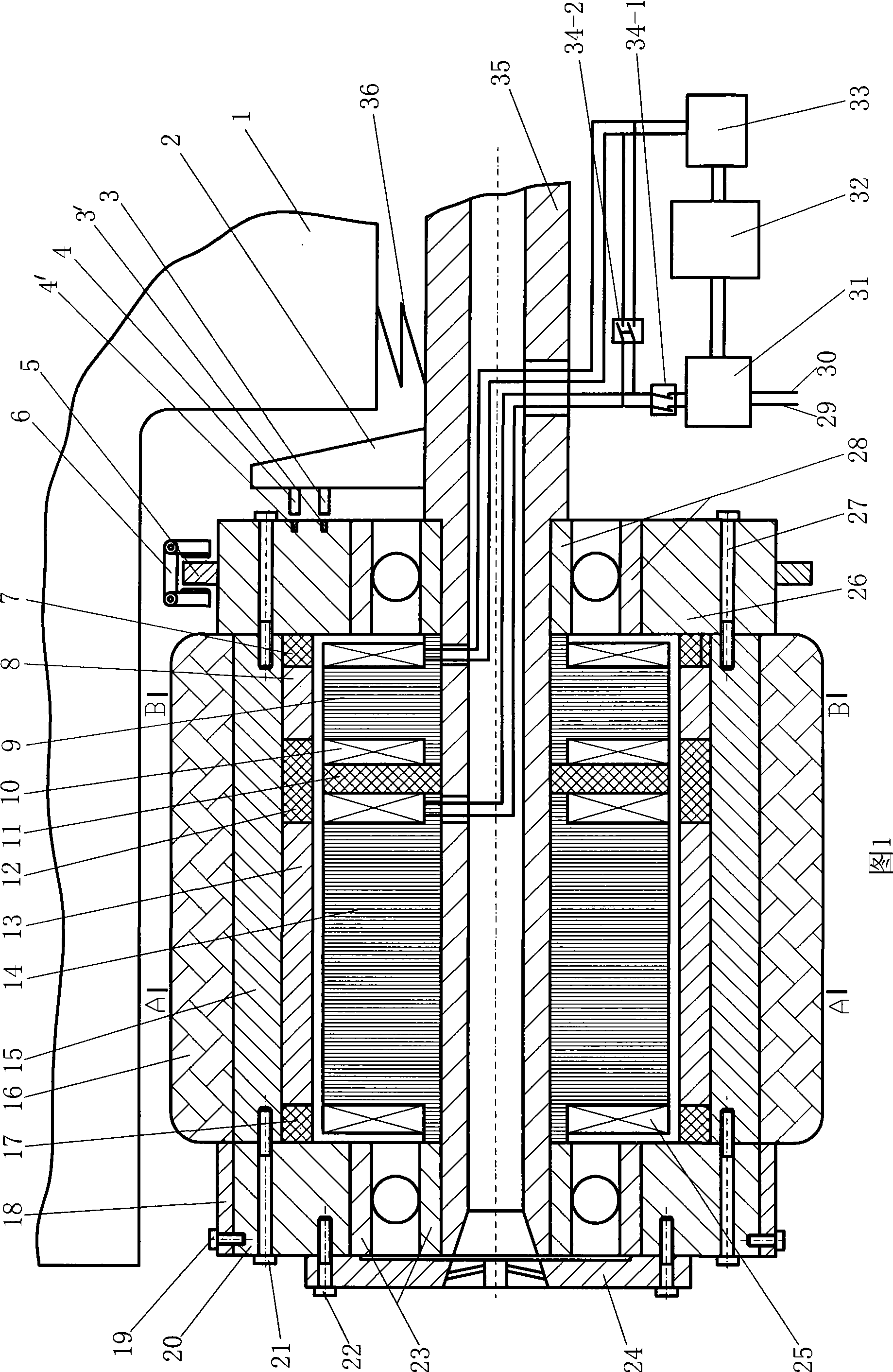
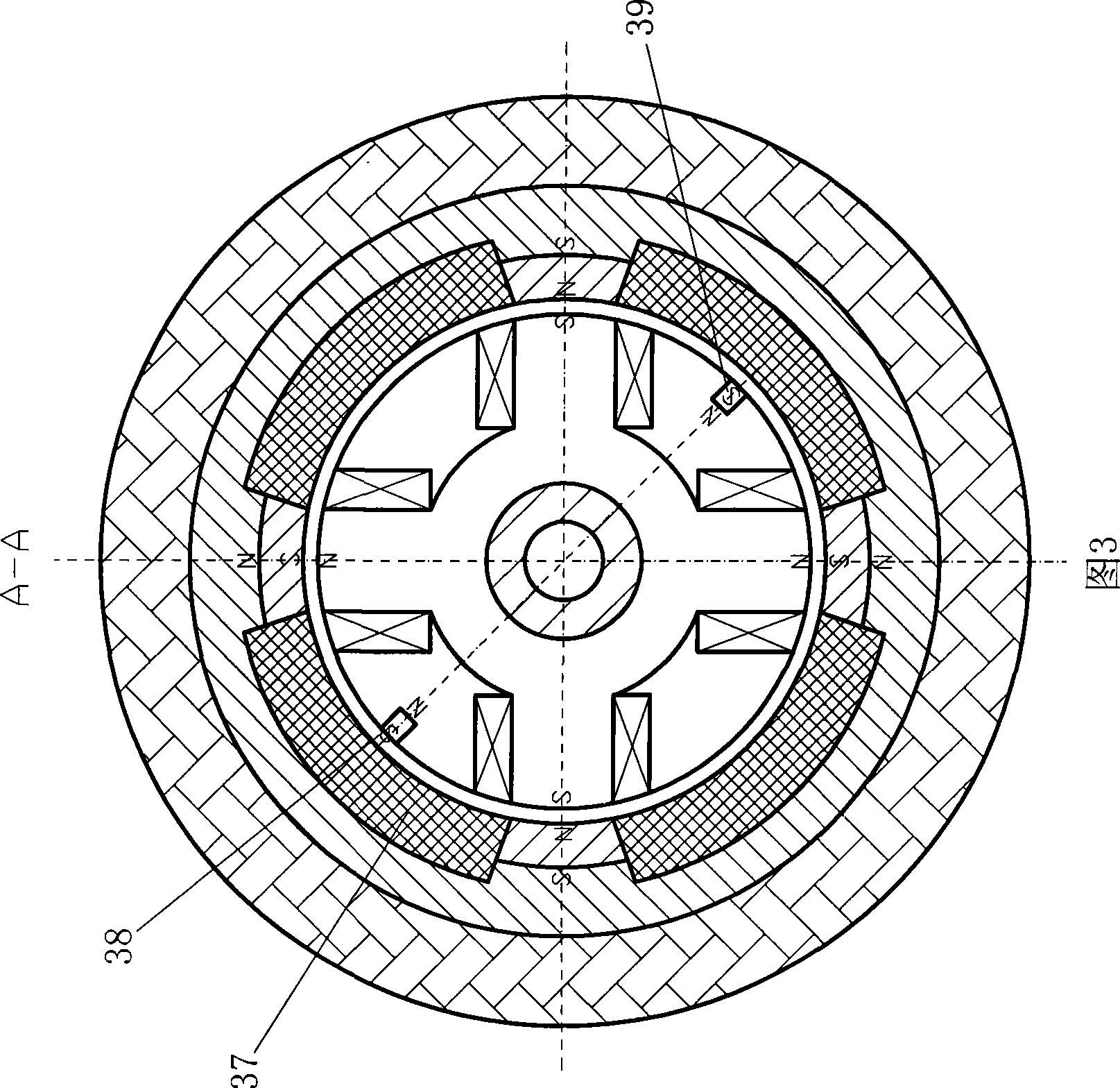
[0029] Embodiment one: as shown in Fig. 1, Fig. 2, Fig. 3, Figure 6 Show. On the fixed shaft 35 with middle hole, solidify the core 9,14 and the non-magnetic insulating spacer ring 11 of the torque gear shape that the soft magnetic sheet is stacked, coils 10,25 are respectively wound on the teeth of the core 9,14, on the stator core 14 is provided with two radially magnetized small permanent magnets 38 and 39, which form the stator.

[0030] Wheel composition: radially magnetized tile-shaped permanent magnets 8, 13 and tile-shaped non-magnetic insulators 37 and non-magnetic insulating rings 7, 12, 17 form a cylinder, four permanent magnets 8, four permanent magnets The magnets 13 are alternately polarized along the circumferential direction, the cylinder is sleeved outside the stator with gaps, and the magnetically permeable hub 15 is fixed on the outer peripheral surface of the cylinder; a number of small magnets are embedded on the circular end plate 26 Columns 3' and 4' f...

Embodiment 2

[0057] Embodiment two: if the magnetic energy vehicle of the present invention often works at a low speed, or in order to reduce the volume and weight of the magnetic energy vehicle of the present invention, remove the magnet 8, stator core 9, coil 10, non-magnetic insulation in the magnetic energy vehicle wheel of the present invention Isolation ring 11, non-magnetic insulating ring 12. The battery system 32 is charged from outside the vehicle and also recovers electrical energy for regenerative braking.

Embodiment 3

[0058] Embodiment three: two magnetic energy machine wheels in front of the magnetic energy vehicle described in embodiment one are replaced with common non-powered wheels, and a four-wheeled vehicle with rear wheel drive is thus obtained.


PUM


Abstract

The invention is composed of a vehicle main body and a control system. The vehicle main body is composed of a vehicle body and a magnetic energy machine wheel, and the control system is composed of a control computer, a bus, a power electronic device, a sensor, a battery system and software. The magnetic energy machine wheel is composed of a stator, a wheel and a bearing, wherein, the wheel rotates around the stator, the stator core is a rectangular gear shape, and the tooth is winded with a coil; a tire, a wheel hub, a magnetizer, a non-magnetic body and a permanent magnet form a multipolar wheel with alternate polarities along the circumference of a circle. The magnetic energy machine wheel comprises two parts: an electric motor and an electric generator. The electric generator is connected with the battery system through a rectifier voltage regulator, and a stator coil is connected with the battery system through a frequency modulator. The control system acquires the position signal of the rotor pole to the stator core tooth according to the sensor, the stator coil is energized with current with different directions alternately, and the wheel is rotated under the actions of the attractive torque and the repulsive torque of the electromagnetic poles of the stator teeth. The invention has the advantages of extremely high efficiency, energy conservation and environmental protection.

Description

technical field [0001] The invention relates to vehicle technology, in particular to a magnetic energy vehicle of a permanent magnet energy motor. Background technique [0002] Traditional vehicles use gasoline, diesel, natural gas, coal gas, liquefied petroleum gas, hydrogen, etc. as fuel internal combustion engines as engines, drive wheels through mechanical transmission mechanisms, and humans operate mechanical direction control mechanisms, speed change mechanisms and braking mechanisms to drive vehicles. Low efficiency, high energy consumption, high noise and exhaust pollution. [0003] Modern electric vehicles reduce the mechanical transmission mechanism, which is mainly realized by wires that occupy a small space, reducing vibration and noise, and the wheel motor has high working efficiency, so the efficiency of the whole vehicle is high; the power electronic device is used for stepless speed change, and the operation is easy , no power interruption and energy loss ca...

Claims


Application Information

Patent Timeline
Patent Type & Authority Applications(China)
IPC IPC(8): B60L11/00H02K7/14H02K7/18
CPCY02T10/641Y02T10/64
Inventor 刘新广
Owner 刘新广
Why Eureka
Try Eureka