High frequency power amplifier and high frequency heating device
A power amplifier and high-frequency technology, applied in the field of high-frequency power amplifiers, can solve problems such as low specific permittivity, difficulty in harmonic control circuits, and reduction, so as to improve power utilization efficiency, improve power utilization, and reduce transmission The effect of loss
- Summary
- Abstract
- Description
- Claims
- Application Information
AI Technical Summary
Problems solved by technology
Method used
Image

Examples
no. 1 approach
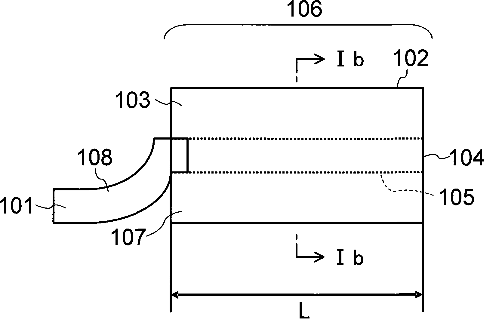
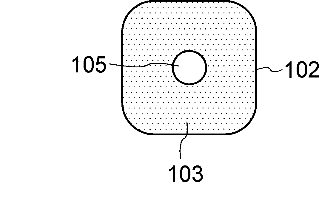
[0103] FIG. 1 shows a side view ( FIG. 1( a )) and a cross-sectional view ( FIG. 1( b )) of a dielectric resonator according to a first embodiment of the present invention.
[0104] As shown in FIG. 1(a) and FIG. 1(b), in the dielectric resonator 106, the bare wire 105 of the signal line is covered by a dielectric material 103, and the periphery of the dielectric material 103 is covered by a grounded external conductor 102.
[0105] Therefore, when an electromagnetic wave is input into the bare wire 105, the input electromagnetic wave is confined in the dielectric resonator 106, and good resonance characteristics with a resonance Q value of 1000 or more can be realized.
[0106] Generally, the transmission loss of a harmonic control circuit that controls harmonics of input electromagnetic waves is determined by the Q value of resonance.
[0107] In the present invention, since the harmonic control circuit is constituted by using a dielectric resonator with a high resonance Q v...
no. 2 approach
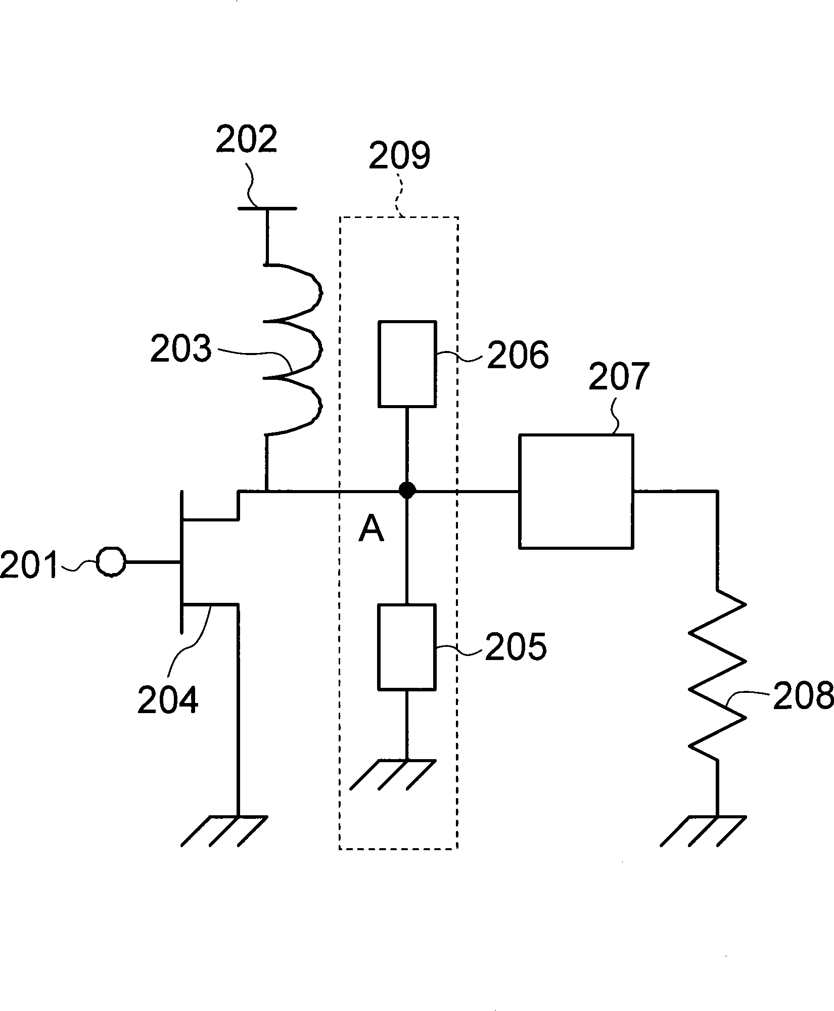
[0116] figure 2 A circuit diagram showing a high-frequency power amplifier according to a second embodiment of the present invention. figure 2 The high-frequency power amplifier is composed of an amplifying element 204 such as a transistor, a harmonic control circuit 209, an output coupling circuit 207, and a load resistor 204 to form a high-frequency power amplifier. Also, 201 is the input end of the high-frequency signal, 202 is the DC bias voltage end for driving the amplifying element 204, and 203 is the choke inductor for the cut harmonic.
[0117] The harmonic signal input from the input terminal 201 of the harmonic signal is amplified in the amplifying element 204 , passed through the harmonic control circuit 209 and the output coupling circuit 207 , and transmitted to the load resistor 208 .
[0118] The output coupling circuit 207 is a circuit for suppressing the coupling loss between the output end of the output coupling circuit and the load resistor 208, and usua...
no. 3 approach
[0129] image 3 A circuit diagram showing a high-frequency power amplifier according to a third embodiment of the present invention. The difference from the second embodiment of the present invention is that the second dielectric resonator 205 whose other end is grounded is replaced by the third dielectric resonator 301 whose other end is open. Here, the third dielectric resonator 301 has one end connected to the output end of the amplifying element 204 through the connection end A, the other end is open, and the axial length is adjusted to be equivalent to 3λ / 8.
[0130] As described in the second embodiment of the present invention, the impedance of the 2nd, 6th, 10th, .
[0131] Furthermore, because the total axial length of the first and third dielectric resonators 206, 301 is equivalent to the length of λ / 2, the fundamental wave component forms an antinode of the amplitude at the open end of the first dielectric resonator 206. The open end of the triple dielectric reson...
PUM
 Abstract
Description
Claims
Application Information
 - R&D
- Intellectual Property
- Life Sciences
- Materials
- Tech Scout
- Unparalleled Data Quality
- Higher Quality Content
- 60% Fewer Hallucinations
Browse by: Latest US Patents, China's latest patents, Technical Efficacy Thesaurus, Application Domain, Technology Topic, Popular Technical Reports.
© 2025 PatSnap. All rights reserved.Legal|Privacy policy|Modern Slavery Act Transparency Statement|Sitemap|About US| Contact US: help@patsnap.com