Annular tube shaped electrode ion trap

A tubular electrode, ion trap technology, applied in circuits, discharge tubes, electrical components, etc., can solve problems such as low resolution of ion traps

Inactive Publication Date: 2009-02-18
FUDAN UNIV
View PDF1 Cites 73 Cited by
  • Summary
  • Abstract
  • Description
  • Claims
  • Application Information

AI Technical Summary

Problems solved by technology

But the resolution of this ion trap is low, about several hundred

Method used


Image

  • Annular tube shaped electrode ion trap
  • Annular tube shaped electrode ion trap
  • Annular tube shaped electrode ion trap

Examples


Embodiment 1

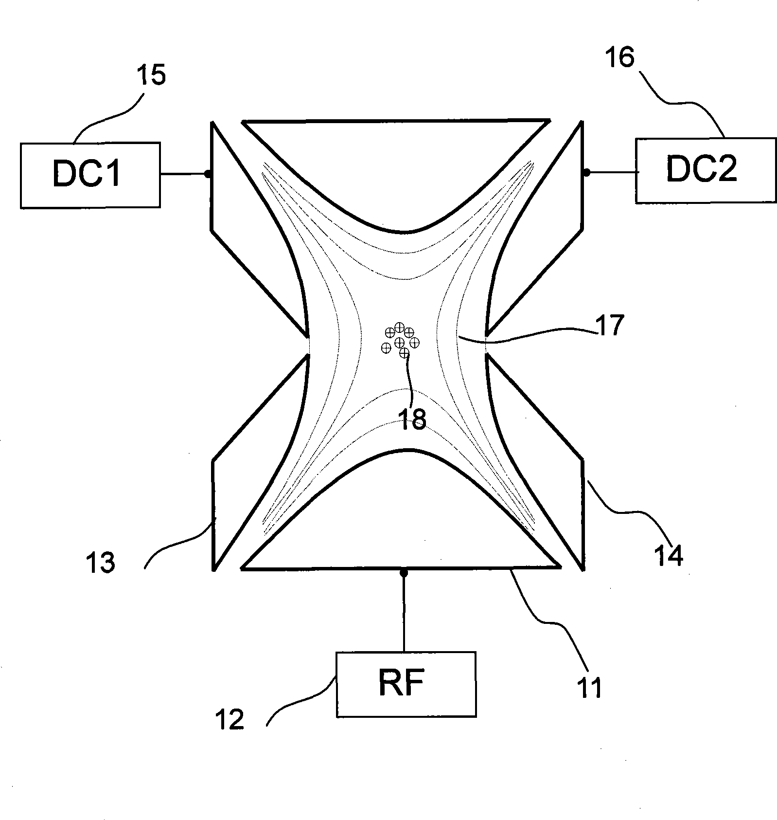
[0060] Figure 9 It is a schematic diagram of the structure of a ring-electrode ion trap mass spectrometer equipped with an electron bombardment ionization source.

[0061] Figure 9 The instrument shown in uses a circular tubular electrode ion trap, and its working process is as follows: thermal electrons generated by the filament 902 enter the circular tubular electrode ion trap through the hole on the plate boundary plate electrode 904, and are accelerated by a DC power supply 906 to Around 70 electron volts. These electrons ionize the molecules 913 of the gas sample to be tested passing into the annular ion trap to generate corresponding ions 914 . At the same time, the DC power supply 906, 907 applies a DC potential with the same polarity as the bound ions on the planar electrodes 904, 905, and the RF power supply 912 simultaneously applies a frequency of several hundred kilohertz to 2 MHz to the inner ring electrode 908 and the outer ring electrode 909. , a radio freq...

Embodiment 2

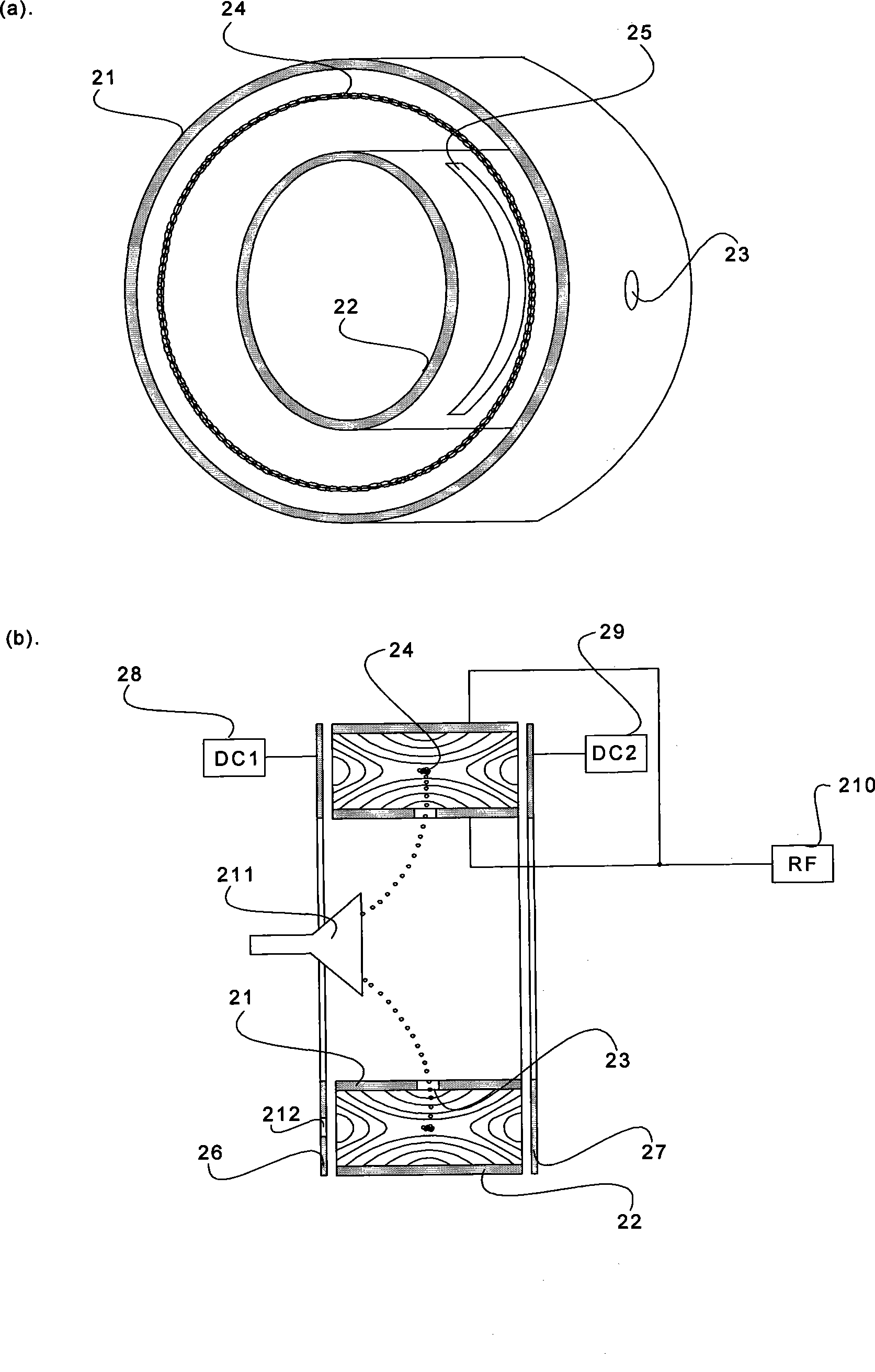
[0072] Figure 10 It is a schematic diagram of an electrospray ionization-quadrupole electrode system-tandem annular ion trap tandem mass spectrometer using a cascaded annular ion trap as a mass analyzer. Figure 10 The structure of cascaded annular tubular ion traps in image 3 shown. Wherein, the surfaces of the annular tubular electrodes 1009, 1010, and 1011 are all made of conductive solid materials and are coaxial.

[0073] Figure 10 The tandem mass spectrometer shown is divided into three vacuum platforms, using a mechanical pump 1015 and molecular pumps 1016 and 1017 respectively. The specific working process is that the ionization source 1002 of the electrosprayer generates the sample ion product 1003 under the action of the high voltage direct current power supply 1001, and enters the guide quadrupole rod 1005 in the primary vacuum cavity through the ion injection port 1004. The gas pressure range of the primary vacuum chamber is 1-150Pa. The sample ions enter t...

Embodiment 3

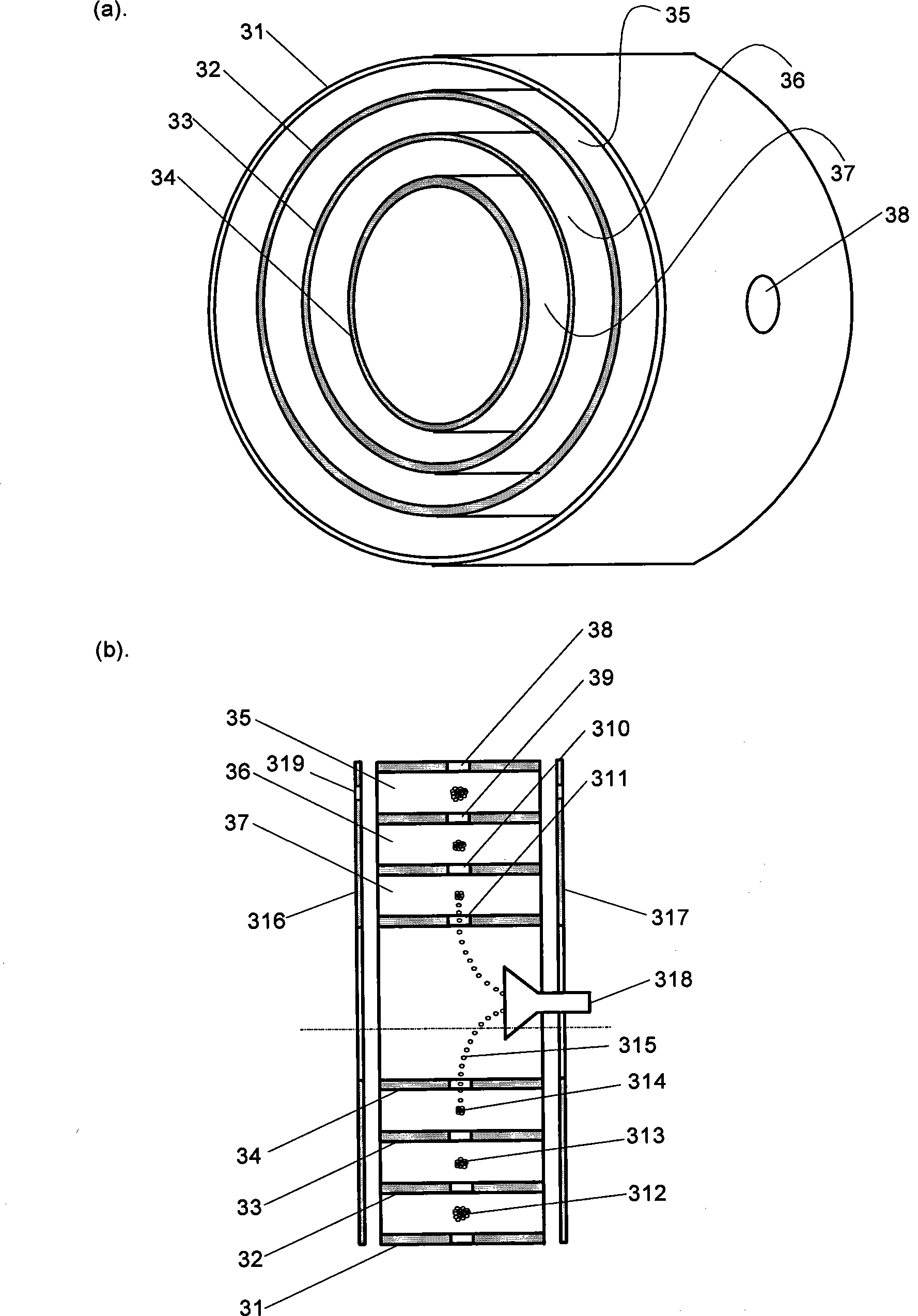
[0081] The ring ion trap can also be used as a pre-analyzer for other high-resolution mass analyzers. Taking time-of-flight mass spectrometry as an example, Figure 11 It is a structural schematic diagram of an electrospray ionization-quadrupole electrode system-annular ion trap-time-of-flight mass analyzer tandem mass spectrometer with an annular ion trap. The instrument system is divided into three vacuum chambers, and the mechanical pump 1115 and the molecular pumps 1116 and 1117 are used to draw vacuum respectively. The specific working process is that the electrospray ionization source 1102 generates sample ion products 1103 under the action of the high voltage direct current power supply 1101 . Sample ion products 1103 pass through a vacuum ion inlet 1104 into a guide quadrupole 1105 in the primary vacuum chamber. The air pressure range of the primary vacuum chamber is 1-150 Pa. The sample ions enter the quadrupole mass analyzer 1107 through the electrode aperture 110...


PUM


Abstract

The invention discloses an annular tubular electrode ion trap used for ion storing and analyzing device, correlating to technology of ion storage and ion mass analysis, especially relates to ion storage and an analysis instrument for analyzing and detecting based on mass-to-charge ratio characteristics of the ion. The annular tubular electrode ion trap has an ion lead-in hole and an ion lead-out hole, two or more annular tubular electrodes of different diameters are assembled together coaxially to compose a set of coaxial annular tubular electrodes, an annular space is formed between two adjacent rings, two plane electrodes are vertical to an axis and are respectively provided on two ends of the annular tubular electrode, boundary electrodes of the ion trap are composed of outer annular tubular electrodes and plane electrodes on two ends, an ion binding area is formed between the adjacent annular tubular electrodes, ions leaded in the area are to be captured, stored or discharged selectively.

Description

technical field [0001] The annular tubular electrode ion trap of the present invention is used in ion storage and analysis devices, and is related to ion storage and ion mass analysis technology, in particular to an analysis instrument for ion storage and analysis and detection according to characteristics such as ion mass-to-charge ratio. technical background [0002] Ion trap is a scientific analysis instrument. It can be used to store the ions of the analyzed samples and perform mass analysis on the ions of the analyzed samples. Ion traps commonly used for ion storage and ion analysis include three-dimensional ion traps and linear ion traps. A three-dimensional ion trap usually consists of a hyperboloid ring electrode and two hyperboloid end electrodes, such as figure 1 shown. When the three-dimensional ion trap is working, an AC high-frequency voltage 12 is applied to the ring electrode 11, or radio frequency voltage, and DC voltages 15 and 16 are applied to the elect...

Claims


Application Information

Patent Timeline
Patent Type & Authority Applications(China)
IPC IPC(8): H01J49/42
CPCH01J49/4255H01J49/4295H01J49/427H01J49/423
Inventor 蒋公羽罗婵李晓旭周鸣飞丁传凡
Owner FUDAN UNIV
Why Eureka
Try Eureka