Phase laser range finder and phase inspecting method thereof

A laser rangefinder and phase type technology, applied in optical radiation measurement, instruments, measurement devices, etc., can solve the problems of affecting detection accuracy, high implementation cost, and high timing stability requirements, and achieve a simple system structure and cost. Low, high measurement accuracy effect

Inactive Publication Date: 2009-03-18
SOUTHEAST UNIV
View PDF0 Cites 14 Cited by
  • Summary
  • Abstract
  • Description
  • Claims
  • Application Information

AI Technical Summary

Problems solved by technology

The digital synchronous detection method of down-sampling and the FFT phase detection method have higher phase detection accuracy. The former requires that the timing of the frequency of the measuring scale must be strictly synchronized with the sampling timing of the ADC (analog-to-digital converter) and conform to a specific proportional relationship. The existing quartz crystal In the filter, if no frequency mixing device is added, it is difficult to find a model that can match the frequency of the measuring ruler and the sampling frequency of the ADC at the same time. Therefore, the filtering quality of the measuring ruler signal is not very good, which directly affects the detection accuracy. Stability requirements are also relatively high; the latter FFT phase detection method needs to meet the Shannon sampling theorem, and the sampling frequency of the ADC is high. If you want to use a lower sampling frequency to achieve FFT phase detection, you need to increase the frequency mixing circuit, and the implementation cost is high; pulse counting The phase detection accuracy of the type phase detection method is not high

Method used


Image

  • Phase laser range finder and phase inspecting method thereof
  • Phase laser range finder and phase inspecting method thereof
  • Phase laser range finder and phase inspecting method thereof

Examples


Embodiment Construction

[0024] specific implementation plan

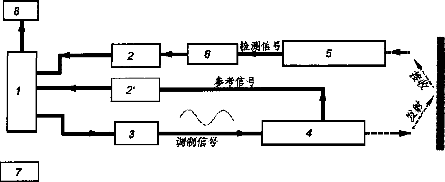
[0025] Such as figure 1 As shown, the overall module of the present invention includes a signal sampling processing control module 1, a first signal amplification and filtering module 2, a second signal amplification and filtering module 2', a measurement ruler signal generation module 3, a laser modulation and emission module 4, and an optical signal receiving and detecting module. Module 5, signal logarithmic converter module 6, power supply module 7, display module 8. Firstly, the measuring ruler signal generation module 3 is controlled by the signal sampling processing control module 1 to generate the first measuring ruler frequency signal, and the signal amplitude modulates the laser tube in the laser modulation transmitting module 4, and the photoelectric monitoring signal of the laser tube is used as a reference signal. After the signal amplification and filtering module 2' filters, it is sampled and processed by the signal sampling ...


PUM


Abstract

The invention discloses a phase type laser range finder and a phase detecting method thereof, belonging to the electronic measurement technical field. The phase type laser range finder comprises a signal sampling control module, a first signal amplifying filter module, a second signal amplifying filter module, a scale signal generation module, a laser modulation launching module, a light signal receiving detection module, a signal logarithmic converter, a power module and a display module. The phase detecting method comprises: selecting a system down sampling frequency, finding sampling data length, grouping sampling data, calculating phase shift and distance. The phase type laser range finder adopting the phase detection method can utilize a quartz crystal filter to filer the ranging signals, utilize continuous indirect scale frequency and down sampling technique, and combine sampling and signal processing functions on a chip, having simple structure, high measurement accuracy and low cost.

Description

technical field [0001] The invention relates to a laser range finder, in particular to a phase type laser range finder and a phase detection method thereof, belonging to the field of electronic measurement. Background technique [0002] Laser range finder, as a non-contact measuring instrument, has been widely used in the fields of remote sensing, precision measurement, engineering construction, safety monitoring and intelligent control. It is suitable for civil use and has a large market and application prospect. The phase distance measurement method obtains the distance traveled by the light wave by measuring the phase shift generated after the modulated light wave propagates through the air. The phase of the light wave is constantly changing during the propagation process. The higher the measurement frequency is, the higher the theoretical accuracy of distance measurement is, but at the same time, the more difficult it is to realize the system. There are two types of la...

Claims


Application Information

Patent Timeline
Patent Type & Authority Applications(China)
IPC IPC(8): G01S11/12G01J9/00
Inventor 段淋淋崔一平
Owner SOUTHEAST UNIV
Why Eureka
Try Eureka