Spherical involute spiral bevel gear cutting method and machine tool

A technology of spiral bevel gear and spherical involute, which is applied in the direction of gear cutting machine, gear tooth manufacturing tool, gear tooth manufacturing device, etc., can solve the difficulty of adjusting the contact area, the processing gear is not interchangeable, and the spherical involute cannot be obtained. tooth shape etc.

Inactive Publication Date: 2009-03-25
JILIN UNIV
View PDF1 Cites 17 Cited by
  • Summary
  • Abstract
  • Description
  • Claims
  • Application Information

AI Technical Summary

Problems solved by technology

However, since the spiral bevel gears cut by the current gear cutting method cannot obtain a spherical involute tooth shape, there are many insurmountable disadvantages
Such as: the instantaneous speed ratio cannot be constant, the change of the transmission angle affects the sensitivity of the contact area, the adjustment of the contact area is difficult, the processed gears are not interchangeable, etc.

Method used


Image

  • Spherical involute spiral bevel gear cutting method and machine tool
  • Spherical involute spiral bevel gear cutting method and machine tool
  • Spherical involute spiral bevel gear cutting method and machine tool

Examples


Embodiment 1

[0100] Parameter Calculation of Machine Tools and Cutting Gears for Three-Axis Linkage CNC Machining of Spherical Involute Spiral Bevel Gears

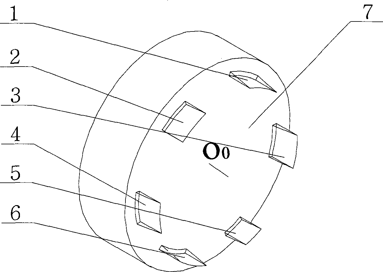
[0101] refer to Figure 5 and Figure 8 , The three-axis linkage CNC machining spherical involute spiral bevel gear machine tool is composed of a cutter head assembly 8, a bed 9, a cradle shaft assembly 10, a gear blank box 11, a turntable 12, and a slide table 13. Wherein the cutter head assembly 8 includes the cutter shaft O 0 , Installed on the cutter shaft O 0 The cutting tooth cutter head 7, eccentric mechanism etc. on. The gear blank box 11 is installed on the top of the turntable 12 to form a sliding connection, and the gear blank box 11 is equipped with a gear blank shaft O 1 , the slide table 13 equipped with the gear blank box 11 can move through the bottom of the slide table 13 and the chute and the slide rail above the turntable 12 (the symmetrical line of the chute and the slide rail and the gear blank axis O 1 The ax...

Embodiment 2

[0105] Parameter Calculation of Machine Tools and Cutting Gears for Four-axis CNC Machining of Spherical Involute Spiral Bevel Gears

[0106] refer to Figure 9 , cutter axis O 0 Installed on the vertical slide 14, the knife axis O 0 The axis of rotation is perpendicular to the vertical slide plate 14 (in Figure 9 -a middle cutterhead axis O 0 Projected as a point), the gear cutting cutter head 7 is fixedly installed on the cutter shaft O 0 On one end of the tool axis O 0 The other end of the vertical slide plate 14 is connected with the independent servo drive system, and the vertical slide plate 14 and the column 15 can be connected through the chute, the slide rail and the thread pair, and the vertical slide plate 14 can move up and down along the Z direction on the column 15, so it is installed with Cutter axis O of gear cutting cutter head 7 0 It can move up and down along the Z direction on the column 15 with the vertical slide 14, and the column 15 is fixedly ins...


PUM


Abstract

The invention discloses a cutting method for a bevel gear with spherical involute toothed circular arc teeth and a machine tool thereof. The cutting method comprises a circular arc cutter edge conjugation generating method and an envelope method. A cutter shaft and a gear blank shaft for implementing the circular arc cutter edge conjugation generating method rotate directionally with rotating rates (Omega0) and (Omega1), a cutter edge enters into cutting, a cage chair rotates according to that Omega is equal to Omega1sinaDeltab, the formation of pure rolling of a gear blank base cone and the big circular plane of the spherical surface is guaranteed to complete the processing of spherical involute toothed flank. The cage chair with a real axis is driven to rotate by a servo motor, and for the cage chair without a real axis, the synthesis movement of the y and z directions of a coordinate system forms a cage chair to rotate with the rotating rate (Omega). When the envelope method is implemented, cutter teeth of short arc and even point cutter edge are adopted. Points with the number of k are taken on the circular arc line AC of generating the flank, each cutting can form a spiral line on the flank, the circular arc cutting feed angle Delta Theta of a gear cutter head per cutting is set, and the flank which is composed of spiral lines with the number of k is enveloped and generated by sequentially k-times cutting feed. A third shaft and a forth shaft link a numerical control gear cutting machine to implement the gear cutting method.

Description

technical field [0001] The invention relates to a device for processing spiral bevel gears and a gear cutting processing method, more specifically, it relates to a gear cutting method and a machine tool for processing spherical involute tooth-shaped spiral bevel gears. Background technique [0002] Bevel gears are important transmission elements that transmit the motion and power of intersecting shafts. Theoretically, for a pair of bevel gears with correct conjugate transmission, the cone tops of the two gears are at the same point, and only the points on the tooth surface that are equidistant from the cone tops can contact each other, that is, the points on the conjugate tooth profile must be on the same spherical surface. Therefore, the profile of the tooth surface of the bevel gear should be a spherical involute. However, the spherical involute cannot be developed in the plane, and the theoretical spherical involute tooth shape has always been considered complex in calcu...

Claims


Application Information

Patent Timeline
Patent Type & Authority Applications(China)
IPC IPC(8): B23F9/00B23F21/00B23F23/12
CPCB23F21/22B23F9/10
Inventor 杨兆军彭福华张学成
Owner JILIN UNIV
Why Eureka
Try Eureka