Cam grinding control system and method based on PC and infrared thermal imaging system

An infrared thermal imager and control system technology, applied in the control of workpiece feed movement, grinding machine parts, grinding/polishing equipment, etc., can solve difficult to achieve predetermined requirements, compromise between speed and effect, grinding wheel Complex processing and other issues

Inactive Publication Date: 2009-04-01
SHANGHAI UNIV
View PDF0 Cites 14 Cited by
  • Summary
  • Abstract
  • Description
  • Claims
  • Application Information

AI Technical Summary

Problems solved by technology

At present, empirical adjustment is usually used, and it is often difficult to obtain a compromise in terms of speed and effect; or the method of finite element calculation and computer simulation is used to obtain the processing temperature field, and then the result is reflected in the processing process.
For an asymmetric structure such as a cam, the machining process of the grinding wheel is more complicated, and it is difficult to achieve the predetermined requirements through this open-loop control

Method used


Image

  • Cam grinding control system and method based on PC and infrared thermal imaging system
  • Cam grinding control system and method based on PC and infrared thermal imaging system
  • Cam grinding control system and method based on PC and infrared thermal imaging system

Examples


Embodiment Construction

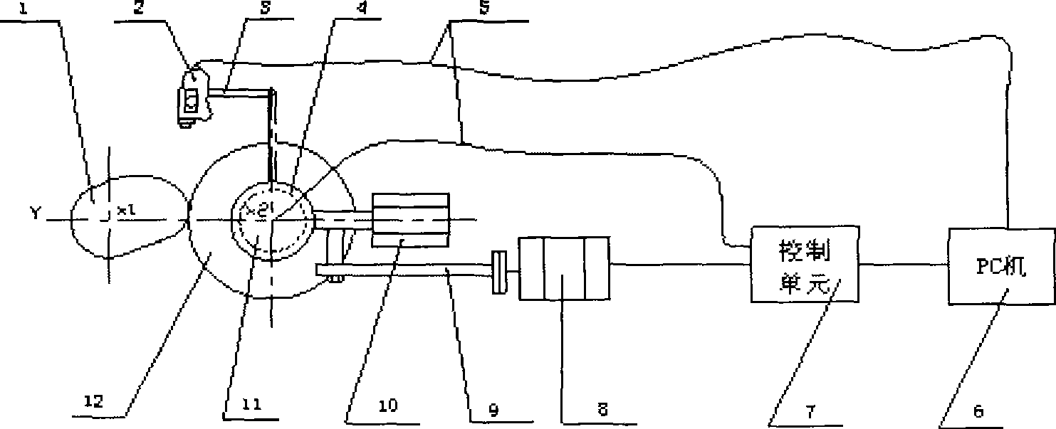
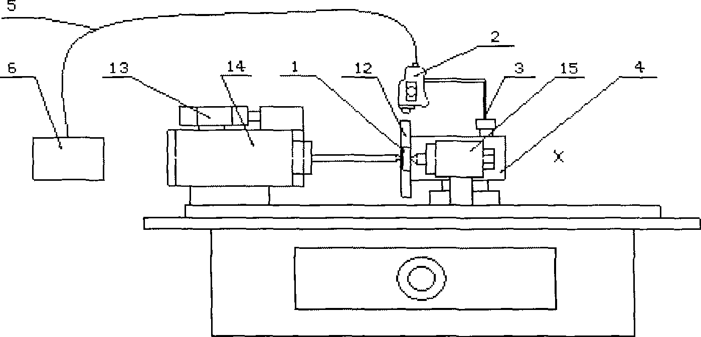
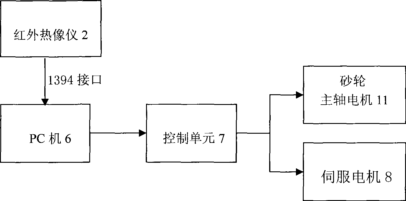
[0015] A preferred embodiment of the present invention is: see Figure 1-3 , This cam grinding control system based on PC and infrared thermal imaging camera, including processed cam 1, infrared thermal imaging camera 2, grinding wheel holder 4, 1394 data interface 5, PC 6, control unit 7, servo motor 8, ball Lead screw 9, linear motor 10, spindle unit 11, grinding wheel 12, connecting rod 3, headstock 14, tailstock 15, headstock motor 13, and other components. The headstock 14 and the tailstock 15 clamp the processed cam 1 so that the cam 1 rotates under the action of the headstock motor 13. The grinding wheel 12 is fixedly connected to the grinding wheel support 4, and performs linear feeding motion under the action of the linear motor 10, the ball screw 11 and the servo motor 8. The spindle unit 11 makes the grinding wheel 12 perform high-speed rotation at the same time. The connecting rod 3 firmly connects the infrared thermal imager 2 and the grinding wheel support 4, so that ...


PUM


Abstract

The invention discloses a cam grinding control system and a method on the basis of a PC and an infrared thermal imager. The system comprises a cam to be processed, a grinding wheel bracket, a PC machine, a control unit, a servo motor, a ballscrew, a linear motor, a mainshaft unit and a grinding wheel; the infrared thermal imager is fixedly connected with the grinding wheel bracket by a connecting rod; the camera of the infrared thermal imager aims at the processing surface of the grinding wheel; the output port of the infrared thermal imager is connected with the PC machine by a 1394 interface; the method uses the temperature field data at the processed area of the grinding wheel measured by the infrared thermal imager as the input variable, and dynamically tracks and adjusts the rotation speed of the grinding wheel mainshaft unit and the feeding quantity of the grinding wheel by a fuzzy control algorithm carried out by the PC machine, thus reasonably applying the grinding process with ensured quality and achieving the control in real time is carried out while the processing efficiency is ensured.

Description

Technical field [0001] The invention relates to a cam grinding control system and method in the field of electromechanical engineering, in particular to a cam grinding control system and method based on a PC and an infrared thermal imager. Background technique [0002] The grinding process has a very high energy input per unit volume of material removed. Almost all of this energy is converted into heat and concentrated in the grinding zone, which leads to an increase in the temperature of the grinding zone. The increase in the grinding temperature has an impact on the surface quality of the cam. Have a great impact. The cam is one of the main components of the internal combustion engine, and its machining quality seriously affects the engine's dynamic performance. When grinding the cam with the numerical control method, the temperature of the grinding zone is the main factor affecting the surface quality of the cam. At present, empirical adjustment is usually used, which is often...

Claims


Application Information

Patent Timeline
Patent Type & Authority Applications(China)
IPC IPC(8): B24B49/12B24B49/14B24B19/12
Inventor 陈荣莲汪地王琦胡志宏王秀荣程维明
Owner SHANGHAI UNIV
Why Eureka
Try Eureka