Method for producing wear-resistant composite roller

A manufacturing method and technology of composite rolls, which are applied in the direction of rolls, metal rolling, manufacturing tools, etc., can solve the problems affecting the normal use of combined composite rolls, prone to pores on the bonding surface, and reduce the strength of the bonding layer, etc., so as to improve the bonding effect , shorten the processing time, improve the effect of bonding strength

Inactive Publication Date: 2009-04-22
BEIJING UNIV OF TECH
View PDF4 Cites 28 Cited by
  • Summary
  • Abstract
  • Description
  • Claims
  • Application Information

AI Technical Summary

Problems solved by technology

The high-carbon high-alloy semi-steel obtained by this invention has a matrix structure mainly of bainite, carbide and pearlite, so it has high wear resistance, but during the centrifugal compounding process of the working layer and the inner layer, pores are prone to appear on the joint surface , inclusions, cracks and other casting defects reduce the strength of the bonding layer and also affect the normal use of the combined composite roll

Method used


Image

  • Method for producing wear-resistant composite roller
  • Method for producing wear-resistant composite roller
  • Method for producing wear-resistant composite roller

Examples


Embodiment 1

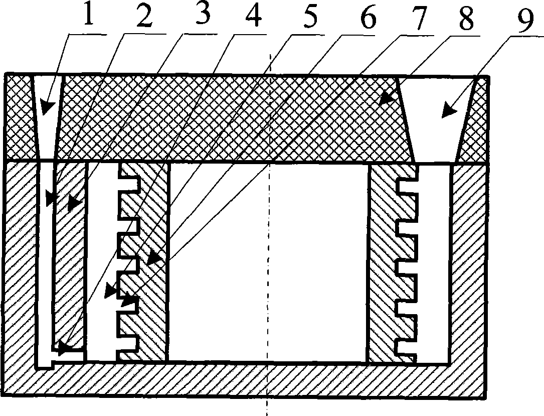
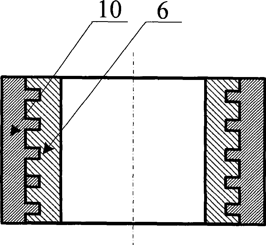
[0028] 1) Process the steel pipe into the roller ring inner sleeve 6, and open a plurality of grooves 7 on the outer surface of the roller ring inner sleeve 6, the groove width is 12mm, the groove depth is 10mm, and the groove spacing is 20mm;

[0029] 2) Soak the inner sleeve 6 of the roller ring with dilute hydrochloric acid to remove impurities and scale on the outer surface, rinse it in alcohol, take it out and dry it naturally, and coat the outer surface of the inner sleeve 6 and the groove 7 with a layer of Thickness 1.0 borax, after natural drying, place in cavity 5 of cast iron metal mold 3;

[0030]3) The outer wear-resistant metal melt enters the cavity 5 through the sprue cup 1, the sprue 2, and the inner runner 4, and the outer wear-resistant metal 10 is poured by the bottom pouring method, and the outer wear-resistant metal 10 is made of high Carbon high-speed steel, the specific composition is as follows (% by weight): 1.93% C, 4.07% Cr, 5.21% W, 4.06% V, 2.04% M...

Embodiment 2

[0033] 1) Process the steel pipe into the roller ring inner sleeve 6, and open grooves 7 on the outer surface of the roller ring inner sleeve 6, the groove width is 15mm, the groove depth is 10mm, and the groove spacing is 25mm;

[0034] 2) Soak the inner sleeve 6 of the roller ring with dilute hydrochloric acid to remove impurities and scale on the outer surface, rinse it in alcohol, take it out and dry it naturally, and coat the outer surface of the inner sleeve 6 and the groove 7 with a layer of Borax with a thickness of 0.82mm is placed in the cavity 5 of the cast iron metal mold 3 after being dried naturally;

[0035] 3) The outer wear-resistant metal melt enters the cavity 5 through the sprue cup 1, the sprue 2, and the inner runner 4, and the outer wear-resistant metal 10 is poured by the bottom pouring method, and the outer wear-resistant metal 10 is made of high Chromium wear-resistant white cast iron, the specific composition is as follows (weight%): 3.06%C, 18.71%Cr...


PUM


Abstract

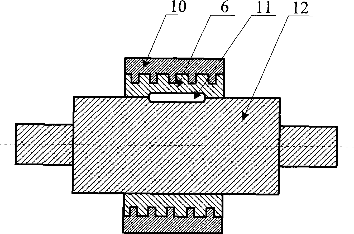
The invention relates to a method for manufacturing a wear resistant composite roll, which belongs to the technical field of steel rolling. The most difficult problems in the technology transfer of the prior combined composite roll are the improvement on the processability of an outer-layer roll sleeve and the improvement on the processing efficiency. The method comprises the following steps: opening a groove on the outer surface of a roll collar inner sleeve, washing the roll collar inner sleeve by using diluted hydrochloric acid and alcohol, then painting borax on the surface of the roll collar inner sleeve and in the groove, and air-drying the roll collar inner sleeve and placing the roll collar inner sleeve in a casting mould; pouring outer layer wear resistant molten metal through a bottom pouring method to obtain an imbedded composite roll sleeve; and combining the imbedded composite roll sleeve with a cast steel or forged steel rolling shaft through splines and integrating the imbedded composite roll sleeve and the cast steel or forged steel rolling shaft through interference fit so as to obtain the wear resistant composite roll. The composite roll has the advantages of high hardness for the outer surface layer, good wear resistance, high roll core strength, good tenacity, firm combinations between the roll sleeve and the roll core and between the roll sleeve outer surface layer and the roll collar inner sleeve and the like.

Description

technical field [0001] The invention belongs to the technical field of steel rolling, and in particular relates to a method for manufacturing a wear-resistant composite roll, in particular to a method for manufacturing a wear-resistant composite roll formed by combining a roll core and a wear-resistant composite roll sleeve. Background technique [0002] It is an effective measure to solve the problem of roll breakage in steel rolling production by using combined composite rolls instead of cast composite rolls. The combined composite roll is an interference fit between the outer layer (roller sleeve or roll ring) and the core (roller shaft) of the roll. In order to ensure the torque required for rolling steel, it is usually necessary to open a keyway or process a threaded hole on the inner side of the roll sleeve. , through splines or bolts, the roller sleeve and the roller shaft are firmly combined. The use of combined compound rolls has a good effect on solving broken rol...

Claims


Application Information

Patent Timeline
Patent Type & Authority Applications(China)
IPC IPC(8): B22D19/16B21B27/02
Inventor 符寒光雷永平吴中伟林健邢建东
Owner BEIJING UNIV OF TECH
Why Eureka
Try Eureka