
Optical fiber line array digital element, device and imaging method thereof

A technology of optical fiber lines and photoelectric devices, which is applied in the field of optical fiber image transmission and digital imaging, can solve the problems of image transmission optical fiber taper consistency and splicing accuracy, large background stray light, high cost, etc., to achieve good optical process performance, The effect of improved resolution and good stability

Inactive Publication Date: 2010-09-29
SOUTH CHINA UNIV OF TECH
View PDF3 Cites 0 Cited by
  • Summary
  • Abstract
  • Description
  • Claims
  • Application Information

AI Technical Summary

Problems solved by technology

The above-mentioned first optical fiber digital structure and technology uses 2×2 identical fiber cones to realize large-scale focal plane devices, which is effective for area array expansion (other technologies are mostly used to improve image quality), but this method is in In the specific implementation, the consistency and splicing accuracy of the image transmission fiber taper are very high. It is generally used in the staring plane imaging optical system. The method is to combine multiple image transmission fiber tapers and multiple area array digital devices to form a large-sized focal plane. devices, but it is very difficult to manufacture high-precision image-transmitting fiber cones, which makes it difficult to guarantee its consistency and is extremely expensive. It is also not applicable when this structure is used as a large-scale one-dimensional focal plane linear array device.
The second method uses optical fiber conversion elements to realize the use of area array digital devices to realize large-scale linear array digital devices. However, in the actual implementation, the accurate connection between the area array device and the area array optical fiber is high, and a large background is likely to be generated during coupling. Stray light, the arrangement of the image transmission fiber is also relatively complicated, because the difference in the length of the conversion fiber will cause uneven brightness of the image surface

Method used


Image

  • Optical fiber line array digital element, device and imaging method thereof
  • Optical fiber line array digital element, device and imaging method thereof
  • Optical fiber line array digital element, device and imaging method thereof

Examples


Embodiment

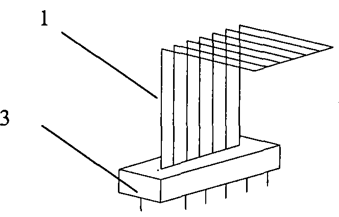
[0034] like figure 1As shown, the optical fiber linear array digital element of the present invention includes an image transmission optical fiber element (1) and a linear array optoelectronic device (3), wherein, the image transmission optical fibers in the image transmission optical fiber element (1) are arranged in sequence, and the transmission The end face of the receiving end of the optical fiber element (1) can be a plane or a curved surface; the end face of the output end of the image transmission optical fiber element (1) can be directly coupled with the photosensitive surface of the linear array optoelectronic device (3), or can be connected with the optical fiber through a lens. The photosensitive surface of the linear array photoelectric device (3) is coupled.

[0035] The optical fiber linear array digital element of the present invention can also include a fixing element for fixing the image-transmitting optical fiber element (1), the fixing element is used for f...


PUM


Abstract

The invention provides an optical fiber linear array digital element and an optical fiber linear array digital device and an imaging method thereof, wherein, the optical fiber linear array digital element comprises an image guide fiber element and a linear array photoelectric device, image guide fibers in the image guide fiber element are arranged in sequence, an end face of the receiving end of the image guide fiber element is a plane or a curved surface, an end face of the output end is closely coupled with a photosensitive surface of a linear array photoelectric device by a lens or directly coupled with the photosensitive surface; a large optical fiber linear array digital device consists of a plurality of optical fiber linear array digital elements and can be used for scanning imagingor position imaging, various image guide fiber elements are arranged in sequence, various receiving end of the image guide fiber elements are connected in sequence to form a combined receiving end ofthe large optical fiber linear array digital device, and the scanning sequence of various linear array photoelectric devices corresponds to the array arrangement sequence of the image guide fibers. The large optical fiber linear array digital device has a conveniently realized structure and excellent cost performance, can be used as an image sensor in aerospace remote sensing and can also be usedfor reading characters and graphics and precision dimension detecting.

Description

technical field [0001] The invention relates to the technical field of optical fiber image transmission and digital imaging, in particular to an optical fiber linear array digital element, device and imaging method thereof. Background technique [0002] Array focal plane devices, such as CCD and CMOS digital imaging devices, are widely used in digital cameras / cameras, image scanning, aerospace remote sensing, and tracking and positioning. The size, spatial resolution, time resolution, signal-to-noise Ratio is its most important application parameter. Image transmission optical fiber is an optical element that arranges the single filaments of optical fibers in order to realize image transmission. It has been effectively used in night vision devices, medical / industrial endoscopes, and special optical systems. [0003] For some large field of view line scan optical systems, a larger size and higher resolution line array digital device is required. When the number of pixels is ...

Claims


Application Information

Patent Timeline
Patent Type & Authority Patents(China)
IPC IPC(8): G02B6/42G02B6/06H04N5/225
Inventor 马国欣薛永祺向鹏
Owner SOUTH CHINA UNIV OF TECH
Learn More