Nontank shaft type electric resistance furnace smelting magnesium apparatus and smelting magnesium method thereof

A tank shaft type, resistance furnace technology, applied in the field of metallurgy, can solve the problems of high labor intensity, consumption of rare metals, high cost of reduction tanks, etc., and achieve the effects of improving production efficiency, reducing heating time, and improving labor efficiency

Inactive Publication Date: 2009-04-29
孙克本 +1
View PDF4 Cites 8 Cited by
  • Summary
  • Abstract
  • Description
  • Claims
  • Application Information

AI Technical Summary

Problems solved by technology

This Pidgeon method magnesium smelting exists environmental pollution more serious, and the working environment of the staff is worse, the deficiency that labor intensity is bigger, is also unfavorable for implementing the mechanization of technological process, automatic implementation, consumes the rare metal of country in a large amount (Cr in the reducing tank Ni accounts for 24-28%, and Ni accounts for 7-9%). In addit...

Method used


Image

  • Nontank shaft type electric resistance furnace smelting magnesium apparatus and smelting magnesium method thereof
  • Nontank shaft type electric resistance furnace smelting magnesium apparatus and smelting magnesium method thereof
  • Nontank shaft type electric resistance furnace smelting magnesium apparatus and smelting magnesium method thereof

Examples


Embodiment 1

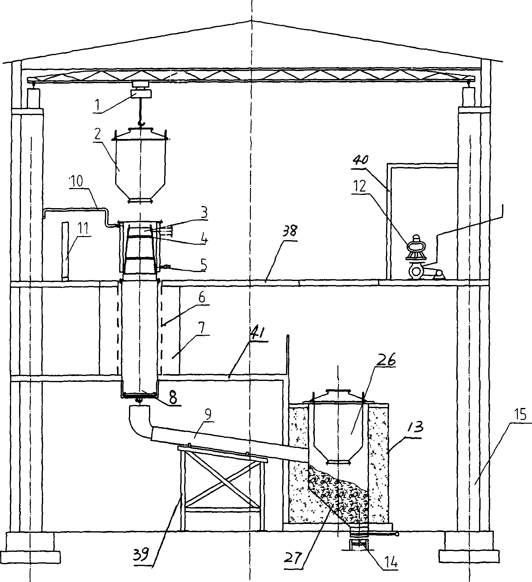
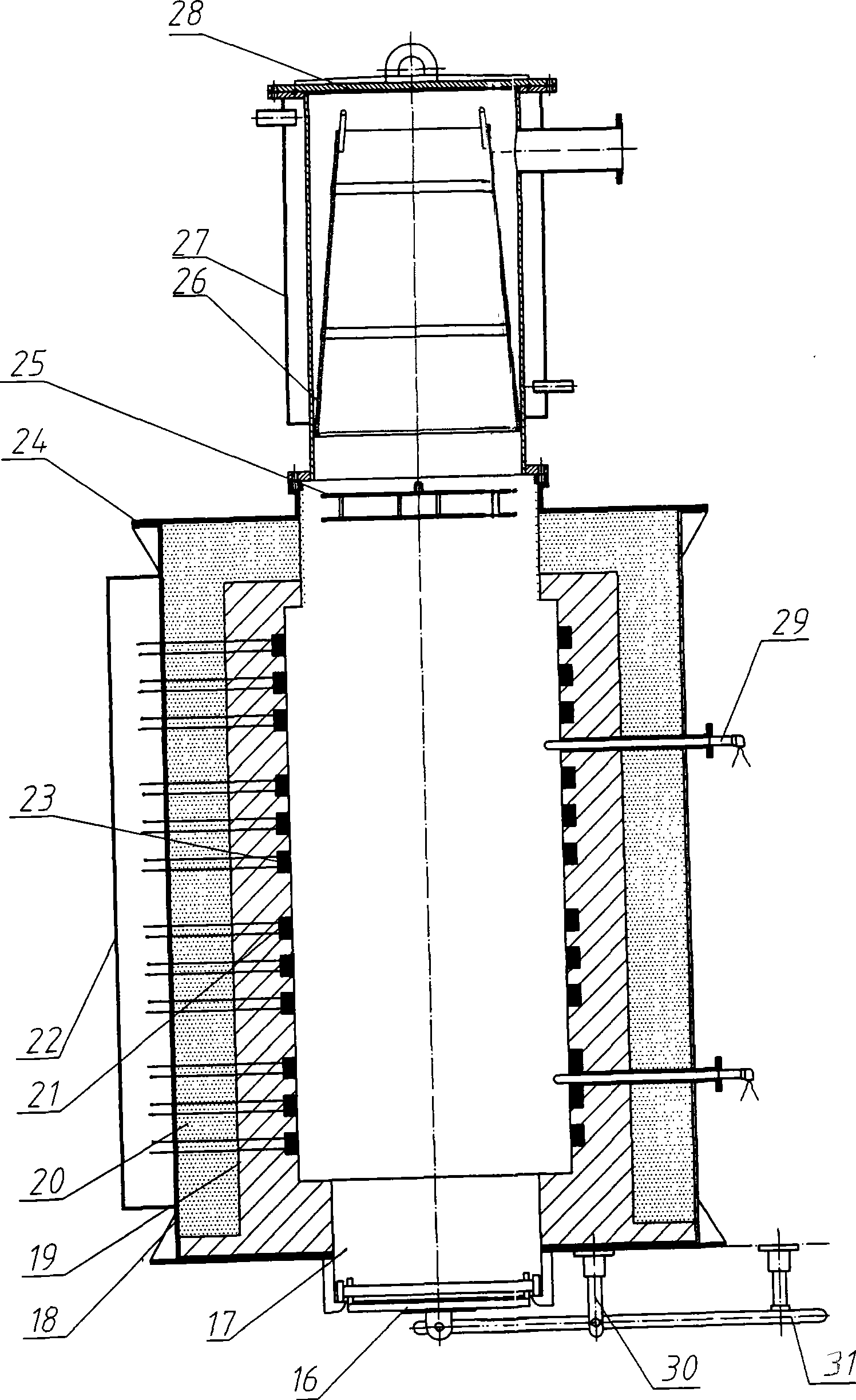
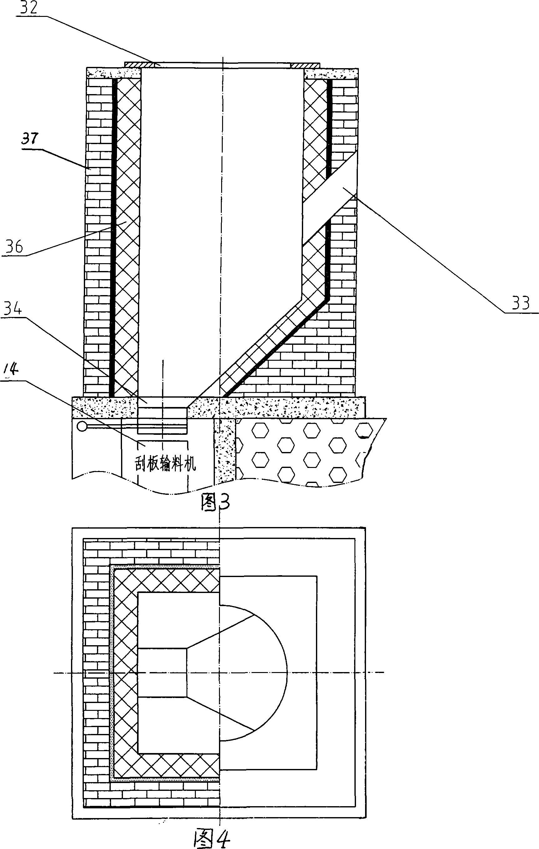
[0027] Embodiment one: figure 1 , figure 2 , shown in Fig. 3, Fig. 4, the tankless vertical shaft type resistance furnace magnesium smelting device of the present embodiment comprises charging tank 2, the lower end of charging tank 2 is provided with crystallizer 3, and the lower end of crystallizer 3 is provided with vertical shaft type resistance furnace 7 , the bottom of shaft type resistance furnace 7 is provided with slag pipe 9, and the bottom of slag pipe 9 is provided with support 39, and one end of slag pipe 9 is connected to charge preheating furnace 13, and preheating tank 26 is set on the preheating furnace mouth 32.

[0028] The charging tank 2 is a fully enclosed cylindrical metal piece with a sealing cover and a slight edge at both ends.

[0029] The crystallizer 3 is a conical metal piece, the periphery of the crystallizer 3 is covered with a water jacket 4, the water inlet pipe 5 and the water outlet pipe 10 are arranged on the water jacket 4, and a water ja...


PUM


Abstract

The invention discloses a pot free vertical shaft type resistance furnace magnesium smelting device, which comprises a charge can. The device is characterized in that a crystallizer is arranged on the lower end of the charge can; a vertical shaft type resistance furnace is arranged on the lower end of the crystallizer; a pipeline is arranged on the bottom of the vertical shaft type resistance furnace; and a furnace charge preheating furnace is connected with one end of the pipe. A pot free vertical shaft type resistance furnace magnesium smelting method comprises the following steps: mixing 84.5 weight percent of calcined dolomite and 15.5 weight percent of ferrosilicon and putting the calcined dolomite and the ferrosilicon into the charge can; pouring the mixed material in the charge can into a furnace cavity through a crane; turning on a power supply to heat the furnace cavity through resistance wire; when the temperature reaches 1,260 to 1,300 DEG C, gasifying the magnesium metal which rises into the crystallizer; and introducing cooling water into the crystallizer to crystallize the magnesium metal into solid magnesium metal when the temperature in the crystallizer is reduced to 400 to 450 DEG C. The greatest difference between the invention and the prior pidgeon process is as follows: the invention disuses an expensive reduction pot made of high alloy refractory steel. The smelting thermal efficiency can be as high as above 90 percent. The pot free vertical shaft type resistance furnace magnesium smelting device has less thermal loss, environmental protection, energy conservation, and less environmental pollution. The device facilitates mechanized production, and can reduce the labor intensity and improve the working environment.

Description

Technical field: [0001] The invention belongs to the magnesium reduction smelting process in nonferrous metal smelting in the field of metallurgy. Background technique: [0002] At present, there are two main types of metal magnesium smelting technologies in the world: one is the chlorination electrolysis magnesium smelting process. Due to the lack of raw material sources, the process of preparing magnesium chloride is more complicated, the power consumption is higher, and the product cost is lower. Higher disadvantages, not adopted. The second is the horizontal tank silicon thermal reduction method, also known as the Pidgeon method for smelting magnesium. This method uses dolomite as raw material, after calcining, the main components are MgO and CaO, under high temperature and vacuum state (3-10pa), ferrosilicon (75%-80% si content) is used to reduce magnesium (vapor state) at 400 Recrystallize around ℃ to obtain crude magnesium with a purity of more than 99.9%. The redu...

Claims


Application Information

Patent Timeline
IPC IPC(8): C22B26/22
Inventor 孙克本
Owner 孙克本
Why Eureka
Try Eureka