
Preionization atmos low-temperature plasma jet generator

A low-temperature plasma and jet generator technology, applied in the direction of plasma, electrical components, circuits, etc., can solve the problems of low batch processing efficiency, maintenance voltage rise, and limited processing efficiency, and achieve long continuous working time and discharge The effect of stabilizing and improving processing efficiency

Inactive Publication Date: 2009-06-24
DALIAN UNIV OF TECH
View PDF0 Cites 47 Cited by
  • Summary
  • Abstract
  • Description
  • Claims
  • Application Information

AI Technical Summary

Problems solved by technology

At present, most low-temperature plasmas are produced by gas discharge at a low pressure of several hundred Pa, but for large-scale industrial production, there are two important disadvantages of low-pressure plasma: (1) the discharge and reaction chamber are in a low-pressure state, Need to use vacuum system, high investment and complicated application
(2) The efficiency of batch processing is low. It is necessary to continuously open the vacuum chamber to take out the finished product and add the test product, and then re-vacuumize and fill the working gas, which is difficult for continuous production.
Traditional atmospheric pressure low-temperature plasma jet devices usually work in He, Ar, O 2 In the mixing of gas and gas, in order to obtain high treatment efficiency, it is hoped that the concentration of chemically active components produced by the jet flow should be as high as possible, but adding too much O to the jet flow 2 It will lead to discharge breakdown and maintenance voltage increase, the discharge is easy to be unstable, and thus transitions to arc discharge, so the processing efficiency is greatly limited

Method used


Image

  • Preionization atmos low-temperature plasma jet generator

Examples


Embodiment

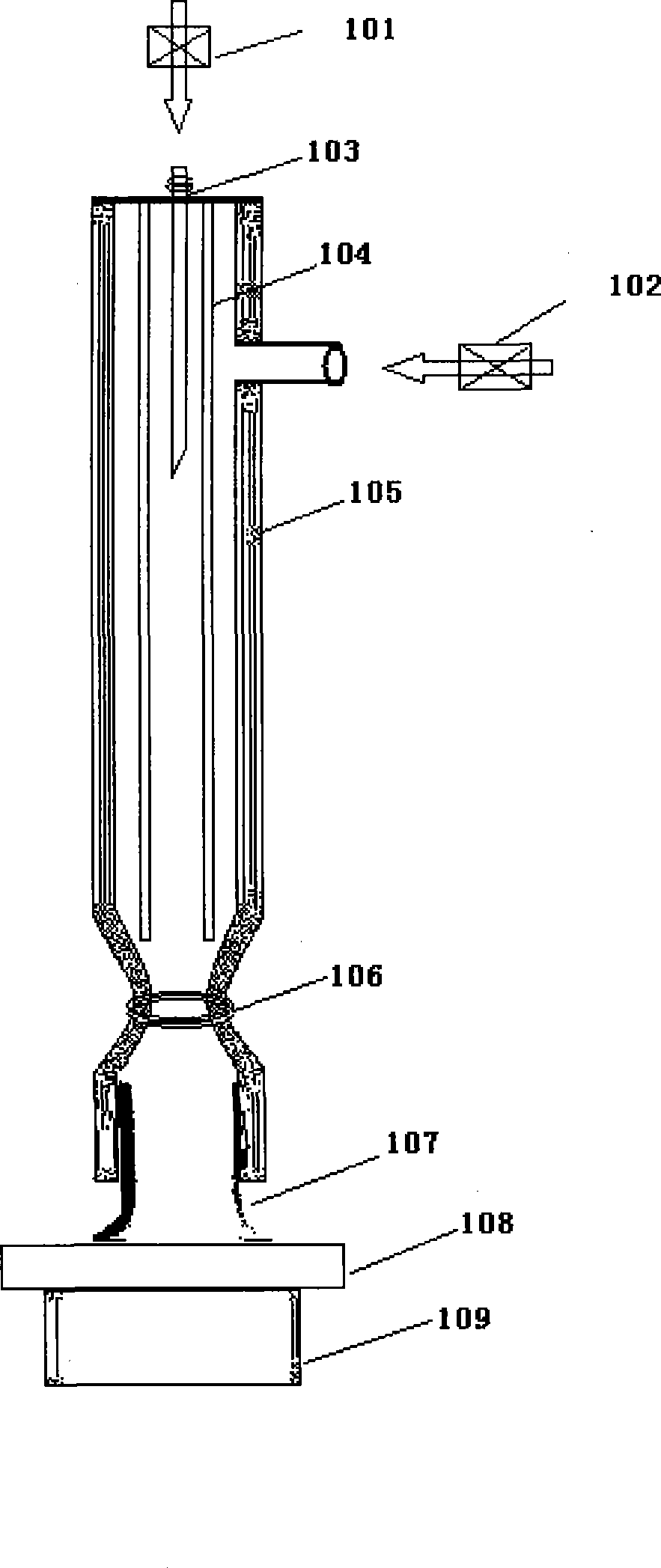
[0023] Choose argon gas (purity 99.999%) as the working gas of single needle electrode, and the lower limit of the flow rate that can produce steady-state jet is 0.08m 3 / h. Using oxygen as the working gas of the ring electrode, the maximum flow rate is 0.13m 3 / h. Now select the argon flow as 0.26m 3 / h, the oxygen flow rate is 0.13m 3 / h:

[0024] 1. When a voltage of 4.0kV is applied, a single-needle pre-ionization discharge is generated, and then the voltage is increased to 8.0kV, and then a ring electrode discharge is generated.

[0025] 2. If the voltage is further increased, the discharge can be maintained stably. The maximum voltage is 12kV. If this voltage is exceeded, the discharge will become unstable, and arc discharge will occur, and the temperature of the discharge plasma jet will rise rapidly.

[0026] 3. Within the parameter range of stable discharge, the measured maximum oxygen atom concentration is 9.8×10 17 / cm 3 .

[0027] 4. Use this device to clean the surfac...


PUM


Abstract

The invention relates to an atmospheric pressure low-temperature plasma jet reactor with preionization structure, which belongs to plasma discharge reactor technical field, and the reactor is characterized in that: the device main body is a millimeter magnitude main silica tube with one open end; a part is arranged above the open end at the lower part with 15 to 25mm, and the part becomes the thinnest at 20mm part, and a ring-shaped electrode is wound on the part; a thin silica tube is connected at the closed end arranged in the inner part thereof through the closed end arranged at the upper part of the silica tube; and a needle electrode is arranged in the thin silica tube. An earthing electrode is arranged below the open end of the main silica tube; and the argon gas is filled into the needle electrode, and the oxygen gas is filled into the main silica tube. The needle electrode and the ring-shaped electrode can be exerted with the same high voltage; the needle electrode discharge can supply the seed electrons for the ring-shaped electrode discharge, and a stable glowing discharge plasma jet is arranged between the ring-shaped electrode and the earthing electrode. The reactor has the beneficial effects that the obtained plasma jet can generate high-concentration chemical activity species, and the reactor has practical value.

Description

Technical field [0001] The invention belongs to the technical field of plasma discharge reactors, and relates to an atmospheric pressure low-temperature plasma jet generator with a pre-ionization structure. Background technique [0002] The ions, electrons, excited atoms, molecules, and free radicals enriched in the low-temperature plasma space are all extremely active reactive species. These active particles are large in number, diverse in types, and highly active, and they are easy to react with the surface of the material they are in contact with. Therefore, in recent years, low-temperature plasma has been used in sterilization, surface modification (improving the properties of paper, film, textiles and fibers in terms of wettability, water absorption, printing and dyeing, adhesion and conductivity), film deposition, and etching. Processing, device cleaning and other fields have been more and more widely used. At present, most low-temperature plasmas are generated by gas disch...

Claims


Application Information

Patent Timeline
Patent Type & Authority Applications(China)
IPC IPC(8): H05H1/26H01J37/32
Inventor 任春生王德真
Owner DALIAN UNIV OF TECH
Learn More