
Sputtering equipment with close packing tip anode

A sputtering equipment and cutting-edge technology are applied in the field of sputtering equipment with close-packed tip anodes, which can solve the problems of limited material preparation cost, negative oxygen ion bombardment, low sputtering efficiency, etc., so as to eliminate the impact of negative oxygen ion bombardment. , the effect of increasing surface area, meeting speed and process window requirements

Active Publication Date: 2011-06-08
GRIMAT ENG INST CO LTD
View PDF1 Cites 0 Cited by
  • Summary
  • Abstract
  • Description
  • Claims
  • Application Information

AI Technical Summary

Problems solved by technology

[0003] Using hollow cylindrical targets for off-axis sputtering can greatly eliminate the impact of negative oxygen ion bombardment, but the sputtering efficiency of hollow cylindrical targets is much lower than that of planar targets, so it cannot meet the requirements of batch production , which greatly limits the cost of material preparation
In batch sputtering preparation, if planar targets can be used for sputtering preparation, it will be much more economical, but the problem of negative oxygen ion bombardment must be solved

Method used


Image

  • Sputtering equipment with close packing tip anode
  • Sputtering equipment with close packing tip anode
  • Sputtering equipment with close packing tip anode

Examples


Embodiment 1

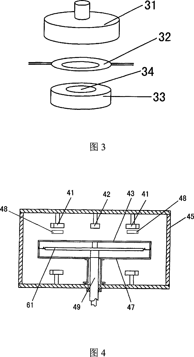
[0030] Such as image 3As shown, Example 1 is a schematic diagram of preparing YBCO high temperature superconducting thin film by static sputtering. Carry out sputtering with the circular YBCO planar target material 31 of φ 68mm, place the close-packed tip anode 32 of circular YBCO sputtering target material at about 20 mm below the planar target material 31 (in image 3 , the close-packed tip body in the close-packed tip anode 32 is not shown and omitted). Opposite to the close-packed tip anode 32 are the oxide single crystal substrate 34 and the heating body 33 of φ 2 ". Generally, a layer of soaking quartz sheet (not shown in the figure) is added between the heating body 33 and the oxide single crystal substrate 34. Shown), in order to play the role of heat uniformity and prevent the sample from bursting due to uneven heating. A positive bias voltage of 50V is applied to the anode end of the close-packed tip.

[0031] During the implementation, at 860°C heating temperatur...

Embodiment 2

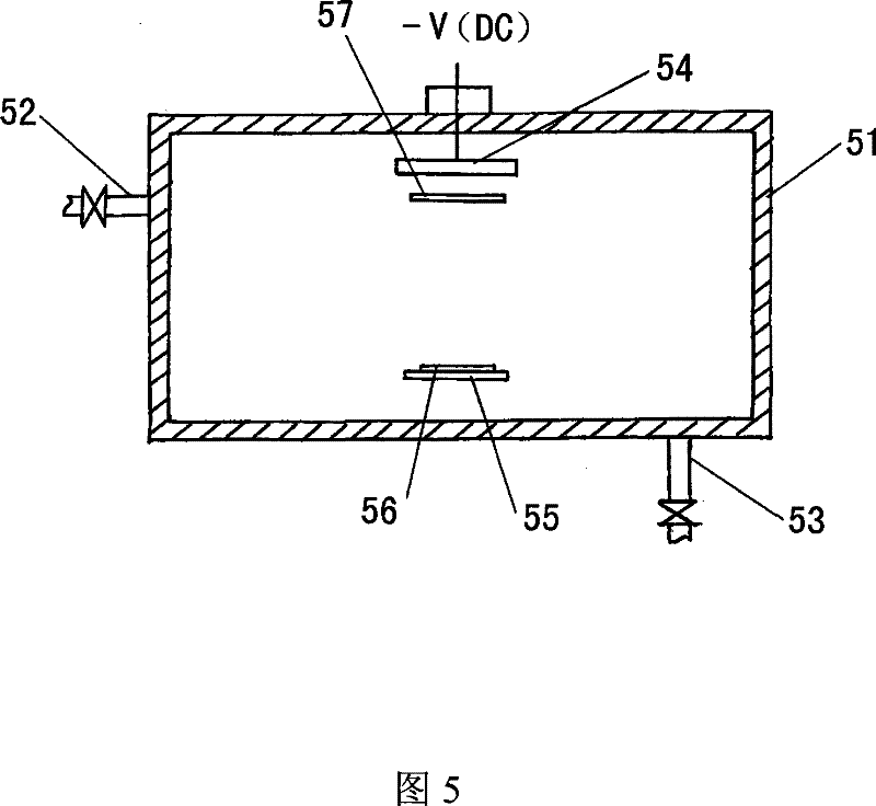
[0034] YBCO high temperature superconducting thin films were prepared by dynamic fixed axis rotation. The equipment disclosed in the patent No. 200620119334.1 entitled "A Device for Batch Preparation of Double-sided High-Temperature Superconducting Thin Films" can be used, such as Figure 4 As shown, the equipment is provided with a planar high-temperature superconducting material target 41 and a metal target 42 for in-situ sputtering electrodes in the vacuum chamber 45; A rotating device, the disc-shaped heating rotating device is composed of a disc rotating device and a disc heating device. The disc heating device includes an upper heating plate 43 and a lower heating plate 47; the disc rotating device is composed of a disc sample stage 61 and a rotating device, and the disc sample stage 61 is evenly spaced for placing large-area superconducting thin films. The circular hole of the substrate (not shown in the figure), the rotating device includes the main rotating shaft 49,...


PUM


Abstract

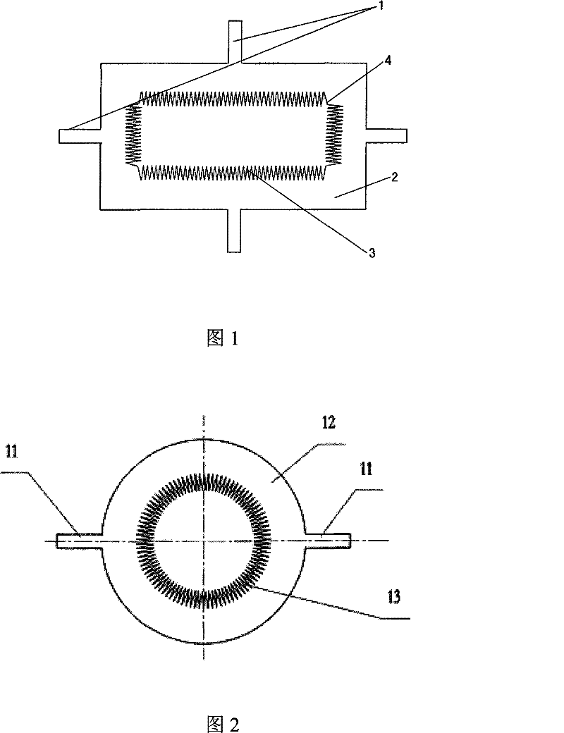
The invention provides a sputtering apparatus with a close packing tip anode. The sputtering apparatus is provided with a vacuum pipeline and an air feeding pipeline on a sputtering cavity body, and the sputtering cavity body is provided with a sputtering target and a heating body inside, wherein the close packing tip anode is arranged between the sputtering target and a sample and takes metal asa basal body, the middle part of the close packing tip anode is hollow, the edge at the inner side of the hollowed-out part is formed by arranging and connecting a plurality of tip bodies continuously, and the tip of each tip body faces the middle part of the hollowed-out part which is opposite to the sputtering target. The sputtering apparatus with the close packing tip anode can be applied to plane target sputtering to prepare an YBCO film material in batch production, greatly removes the influence of the negative oxygen ion bombardment, and meets the requirements on the speed of batch preparation and a process window.

Description

technical field [0001] The invention relates to a sputtering device with close-arranged tip anodes, in particular to a sputtering device with densely-arranged tip anodes used in the preparation of thin films and coatings on large-scale planar oxide targets. Background technique [0002] Preparation of complex oxide thin film materials by sputtering (magnetron sputtering), such as rare earth barium copper oxide, etc., is easily affected by negative oxygen ion reverse sputtering (or negative oxygen ion bombardment), resulting in thin film composition and structure uneven. For rare earth barium copper oxide ReBa 2 Cu 3 o 7-δ (ReBCO, such as YBCO) and other high-temperature superconducting thin film materials, the film composition must meet the ratio of Re:Ba:Cu=1:2:3, in order to meet the performance requirements of high transition temperature, high critical current density, etc., so the removal of negative The impact of oxygen ion bombardment is extremely important for the...

Claims


Application Information

Patent Timeline
Patent Type & Authority Patents(China)
IPC IPC(8): C23C14/35
Inventor 李弢古宏伟王霈文
Owner GRIMAT ENG INST CO LTD
Learn More