Industrial furnace liner

A technology for industrial furnaces and furnace linings, applied in lining support, overall lining and other directions, can solve the problems of reduced furnace sealing and heat preservation, large heat dissipation loss on the surface of the furnace body, and large heat storage loss in the masonry, so as to shorten the furnace laying cycle. , The effect of improving working conditions and simplifying the structure of the furnace body

Inactive Publication Date: 2009-07-01
SHANGHAI HUISEN MTH INDAL FURNACES
View PDF0 Cites 5 Cited by
  • Summary
  • Abstract
  • Description
  • Claims
  • Application Information

AI Technical Summary

Problems solved by technology

[0003] 1. The furnace building period is long;
[0004] 2. The heat storage loss of the masonry is relatively large, and the heat dissipation loss on the surface of the furnace body is relatively large;
[0005] 3. Both insulation bricks and impermeable bricks use lightweight bricks with a specific gravity in the range of 0.5 to 0.8. The obvious disadvantages are

Method used


Image

  • Industrial furnace liner
  • Industrial furnace liner
  • Industrial furnace liner

Examples


Embodiment Construction

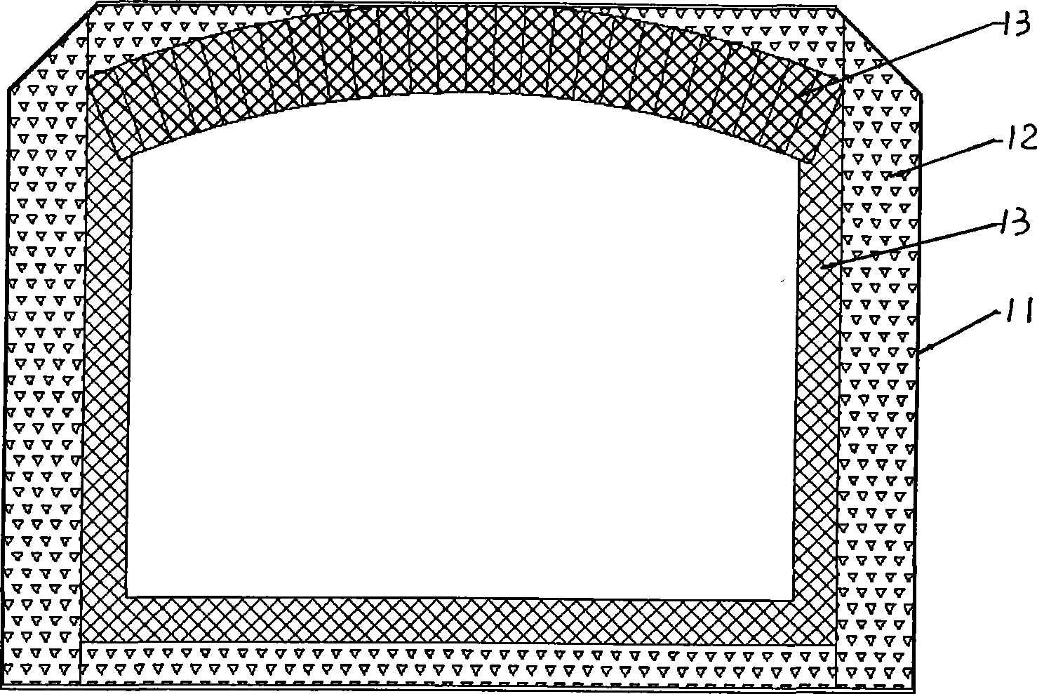
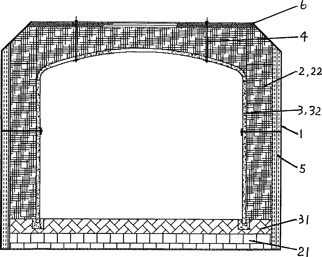
[0020] see figure 2 , image 3 , The industrial furnace lining of the present invention is arranged in the furnace shell 1 of the industrial furnace, and includes an inner high temperature resistant layer 3 and an outer heat insulating layer 2 .

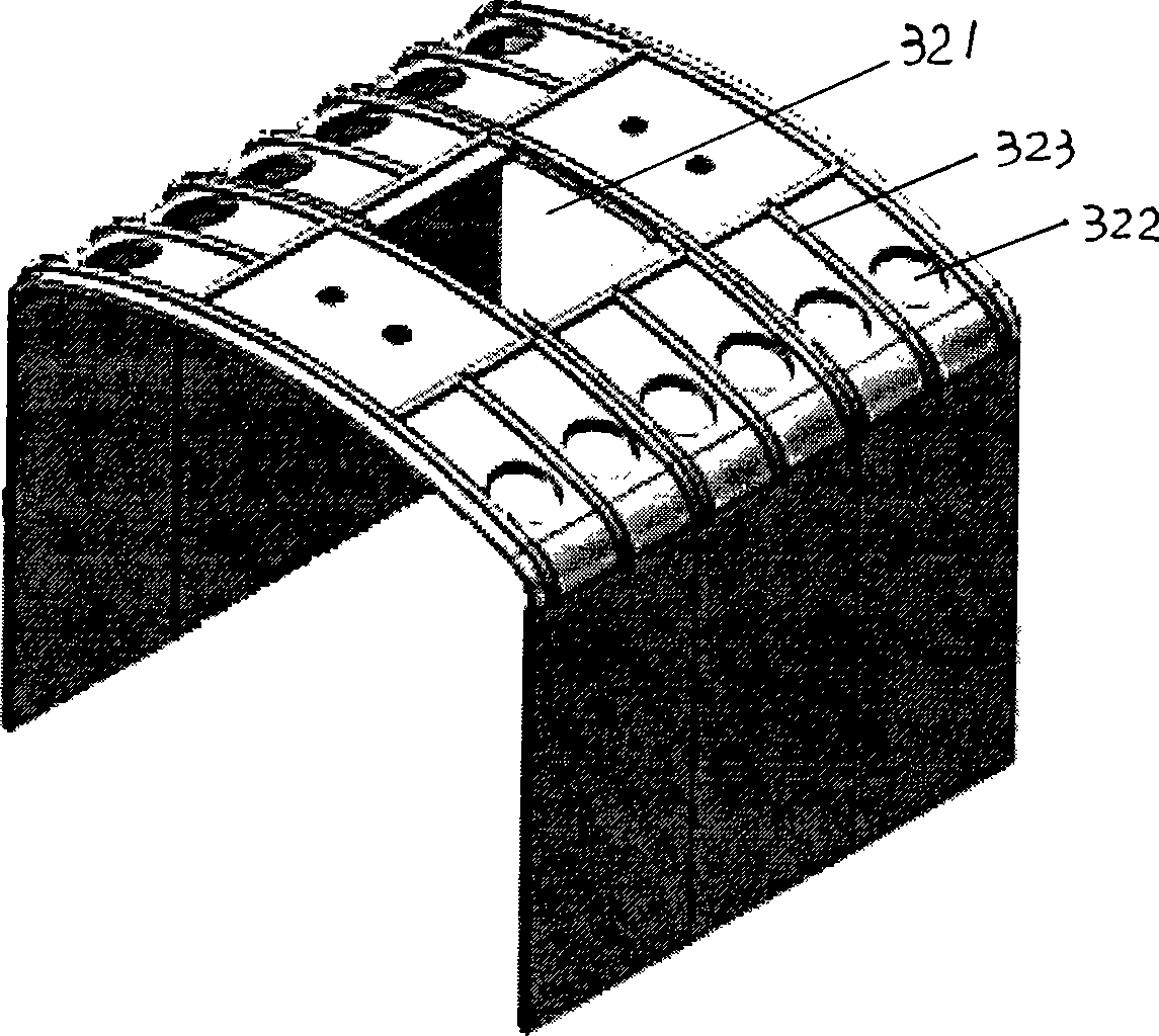
[0021] Cooperate see image 3 , the inner layer high temperature resistant layer 3 comprises the bottom 31 that is built by impermeable bricks, and the lining 32 that is arranged on both sides and top, and this lining 32 is to adopt high temperature resistant non-metallic composite material (this embodiment is silicon carbide / Silicon nitride composite material) made of an integral inverted U-shaped structural member. Both sides of the inner lining 32 of the inverted U-shaped structural member are plate structures, and an air hole 321 is provided in the middle of the top for communicating with the outside world. Rib structure 323 . The inner lining 32 of the inverted U-shaped structure is fixedly connected with the furnace shell...


PUM


Abstract

An industry furnace lining is arranged in the industry furnace shell and comprises an inner high temperature resistant layer and an outer heat-insulating layer, the bottom of the inner high temperature resistant layer is built by impervious bricks, a whole reverse U-shaped structural member made of high temperature resistant non-metal composite material is taken as an inner lining on the two sides and the top; the bottom of the outer heat-insulating layer is built by the insulating bricks, the two sides of the top of the outer heat-insulating layer are built by light high-alumina refractory fiber modules. The industry furnace lining of the invention has advantages of short furnace building period, low maintenance cost and long service life; and can implement the rapid temperature raising and descending of the furnace kiln.

Description

technical field [0001] The invention relates to an industrial furnace cellar, in particular to an industrial furnace lining. Background technique [0002] The industrial furnace lining is set in the furnace shell of the industrial pit furnace, including the inner high temperature resistant layer and the outer thermal insulation layer. The industrial furnace lining of prior art is as figure 1 As shown, its outer layer insulation layer 12 adopts insulation bricks to build on the inner side of furnace shell 11, and inner layer high temperature resistant layer 13 adopts impermeable bricks or high temperature resistant bricks to build on the inside of outer layer insulation layer 12. The problems with this structure and material are: [0003] 1. The furnace building period is long; [0004] 2. The heat storage loss of the masonry is relatively large, and the heat dissipation loss on the surface of the furnace body is relatively large; [0005] 3. Both insulation bricks and im...

Claims


Application Information

Patent Timeline
IPC IPC(8): F27D1/10F27D1/14
Inventor 曾爱群高玉栋刘强倪峻
Owner SHANGHAI HUISEN MTH INDAL FURNACES
Why Eureka
Try Eureka