
Anti-adhering knife/blade with surface micromoulding

A technology of surface micro-modeling and cutting tools, which is used in the manufacture of tools, metal processing machinery parts, maintenance and safety accessories, etc. It can solve the problems of coating material falling off, loss of anti-wear and protection functions, etc., to improve the friction state, inhibit the The effect of sticking to the knife and improving the lubricating effect

Inactive Publication Date: 2009-07-15
NANJING UNIV OF AERONAUTICS & ASTRONAUTICS
View PDF0 Cites 22 Cited by
  • Summary
  • Abstract
  • Description
  • Claims
  • Application Information

AI Technical Summary

Problems solved by technology

However, when processing some difficult-to-machine materials, the coating material of the coated tool will fall off quickly due to the impact and friction during processing, losing the functions of anti-wear and protection, and the ability to inhibit the sticking of the tool is limited

Method used


Image

  • Anti-adhering knife/blade with surface micromoulding
  • Anti-adhering knife/blade with surface micromoulding
  • Anti-adhering knife/blade with surface micromoulding

Examples


Embodiment Construction

[0012] specific implementation plan

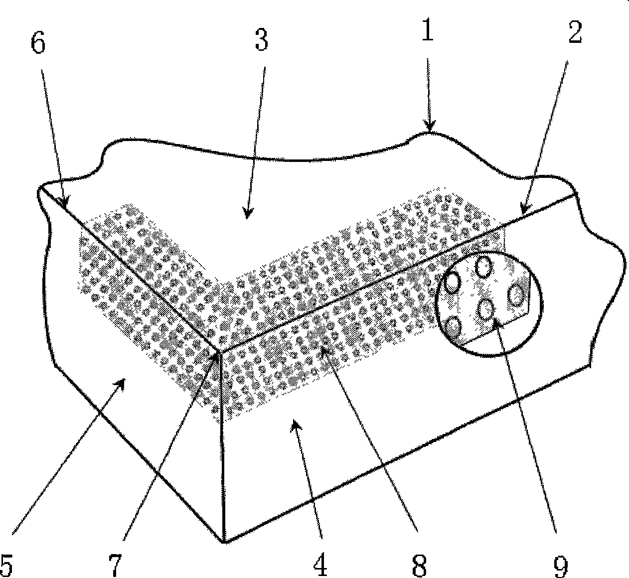
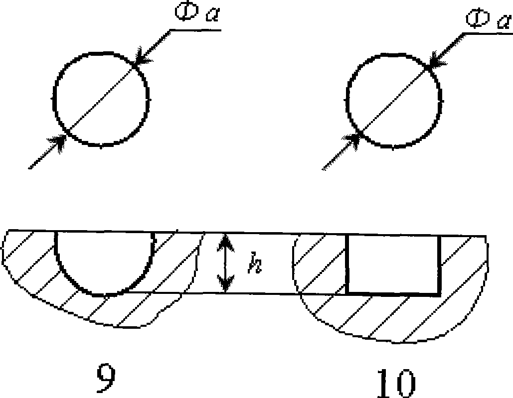
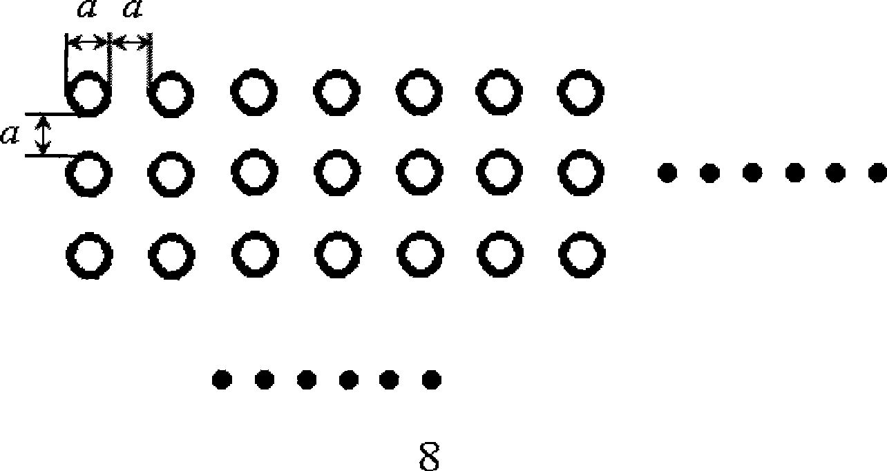
[0013] Such as figure 1 and figure 2 Shown is the anti-bonding and wear-resistant cutting tool with surface micro-modeling of the present invention. In areas where wear is prone to occur, such as the front and flank surfaces near the cutting edge, micro-manufacturing techniques such as electrochemical machining or laser machining are used to process some micro-pit array structures. Such as the micropit structure, the diameter of a single micropit is about 10-80 μm, and the depth is 5-30 μm. The distance between adjacent micropits depends on the distribution, and is generally the size of a micropit diameter. The base material consists of a hard metal material (tungsten carbide, high-speed steel), or a ceramic material.

[0014] In addition, the design of the geometric parameters of the tool surface micro-modeling has an impact on the size of the anti-bonding ability. The geometric parameters of the micromodels include the geometry and ...


PUM


Abstract

The invention relates to a cutter / cutter blade with a slightly formative surface, which has bonding resistance and abrasion resistance and belongs to the filed of the mechanical manufacture of mechanical engineering. The invention is characterized in that a plurality of dimple array structures are distributed in an area which is easy to generate abrasion, such as a front tool face and a rear tool face which are near the neighborhood of a cutting edge, and the dimple array structures are processed by adopting a minuteness manufacturing technique, such as electrochemical processing or laser processing, and the like so as to improve the contact situation of the cutter, cuttings and workpieces during cutting processing and prevent workpiece materials from bonding the cutter. The invention is suitable for various processing methods of the cutting processing, such as turning, milling, drilling, boring, broaching, and the like.

Description

Technical field [0001] The invention relates to an anti-adhesion and wear-resistant cutter / blade with surface micro-modelling, which belongs to the field of mechanical manufacturing in mechanical engineering. technical background [0002] Cutting has always occupied an important position in the field of mechanical processing, and it is still the main processing technology so far. With the advancement of science and technology, the development of high-speed machine tools and the emergence of various new materials, there are more and more researches on cutting tools. [0003] In the cutting process, when the tool cuts the workpiece material, the parts in contact with the workpiece and chips are subject to a large wear load. For example, in turning processing, there is severe friction between the rake face of the tool and the bottom of the chip, and the flank face and the machined surface of the workpiece. In addition to the front and rear facets in milling, sometimes the atta...

Claims


Application Information

Patent Timeline
IPC IPC(8): B23Q11/10
CPCB23B2222/88B23B2250/18
Inventor 李亮何宁卞荣赵威戚宝运王琦
Owner NANJING UNIV OF AERONAUTICS & ASTRONAUTICS
Learn More