Voltage equalizing protection control circuit for series IGBT

A technology for controlling circuits and resistors, applied in the direction of emergency protection circuit devices, electrical components, etc., can solve problems such as static voltage imbalance, switching characteristics and voltage spikes, series IGBT switching loss control circuit control loss, etc., to avoid circuit reliability Sexuality issues, improved efficiency and reliability, and simple circuit structure

Inactive Publication Date: 2012-06-13
HEFEI UNIV OF TECH
View PDF0 Cites 3 Cited by
  • Summary
  • Abstract
  • Description
  • Claims
  • Application Information

AI Technical Summary

Problems solved by technology

[0007] The distributed inductance of the device lead and the characteristics of the absorption circuit of the cascaded device are inconsistent, which will lead to different switching characteristics and voltage spikes. The static voltage is unbalanced, and the device that is turned on after the turn-on process is subjected to an overvoltage that may be several times higher than the normal voltage
At the moment of transition of switching devices, different switching characteristics will also be displayed, which will lead to dynamic voltage imbalance of series devices
[0008] 2. The delay of the gate signal of the series IGBT
However, the switching loss of the series IGBT and the control loss of the control circuit are large

Method used


Image

  • Voltage equalizing protection control circuit for series IGBT
  • Voltage equalizing protection control circuit for series IGBT
  • Voltage equalizing protection control circuit for series IGBT

Examples


Embodiment Construction

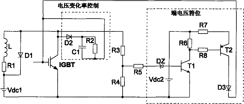
[0036] see figure 1 , for the IGBT device, a voltage change rate control circuit and a terminal voltage clamp control circuit are set;

[0037] figure 1As shown, the voltage change rate control circuit is composed of a unidirectional conduction diode D2, a charging and discharging capacitor C1 and a resistor R2. During the turn-off process of the IGBT, when the voltage at the IGBT terminal is higher than the voltage on the capacitor C1, the diode D2 is turned on, and the capacitor C1 is connected in parallel to both ends of the GC of the IGBT, acting as the external miller capacitor of the IGBT, so that the voltage at the IGBT terminal rises At the same time, since the capacitance C1 is much larger than the IGBT parasitic miller capacitance, the inconsistency of the IGBT's own parameters can be ignored to achieve the function of voltage balance. During the turn-on process, the capacitor C1 is discharged to the set turning point voltage value of the voltage change rate throug...


PUM


Abstract

The present invention discloses a voltage sharing protection control circuit of series IGBT, and the structural feature is the setup of the voltage change rate control circuit and the terminal voltage clamp control circuit, wherein the voltage change rate control circuit is composed by a one-way conducting diode D2, a charge-discharge capacitance C1 and a resistance R2; during switch off time of the IGBT, the conducting diode D2 and the capacitance C1 in charged state constitute IGBT external capacitance parallel to CG end of the IGBT; during conducting time of the IGBT, the capacitance C1 takes resistance R2 as discharge path; the terminal voltage clamp circuit is composed by a triode T1 and T2, the clamp state is that DC passes through triode T2, diode D3 and charge grid capacitance of the IGBT. The present invention constitutes control circuit with simple analog elements, realizes IGBT switch voltage waveform similar to standard curve, and realizes different voltage change rate in different stages of the switch process.

Description

technical field [0001] The invention relates to an IGBT control circuit, more specifically an IGBT control circuit suitable for high-voltage converters in high-voltage direct current transmission systems and high-voltage frequency converters based on IGBT series connections. Background technique [0002] Insulated gate bipolar transistor (Insolated Gate Bipolar Transistor---IGBT) was developed in the early 1980s in order to solve the high turn-on voltage of MOSFET, which was difficult to manufacture with high voltage and high current characteristics and low operating frequency of GTR. A double mechanism composite device (Double Mechanism Device) that appears due to insufficient power of the drive circuit. Because it combines the advantages of MOSFET and GTR, it not only has the advantages of high input impedance, fast speed, good thermal stability, simple driving circuit, small driving current, etc., but also has small on-state voltage drop, high withstand voltage and withst...

Claims


Application Information

Patent Timeline
Patent Type & Authority Patents(China)
IPC IPC(8): H02H7/12
Inventor 张兴蒲道杰孙荣丙刘淳
Owner HEFEI UNIV OF TECH
Why Eureka
Try Eureka