Method and apparatus for producing nanofiber and polymeric web

A technology of nanofibers and polymer nets, applied in fiber processing, nanotechnology, textiles and papermaking, etc., can solve problems such as difficult maintenance, and achieve the effects of easy maintenance, simple manufacturing, and low-cost manufacturing

Inactive Publication Date: 2009-07-15
PANASONIC CORP
View PDF0 Cites 22 Cited by
  • Summary
  • Abstract
  • Description
  • Claims
  • Application Information

AI Technical Summary

Problems solved by technology

However, it would be very difficult to maintain a large number of such elongated nozzles 41 in order to keep them in proper condition

Method used


Image

  • Method and apparatus for producing nanofiber and polymeric web
  • Method and apparatus for producing nanofiber and polymeric web
  • Method and apparatus for producing nanofiber and polymeric web

Examples


Embodiment approach 1

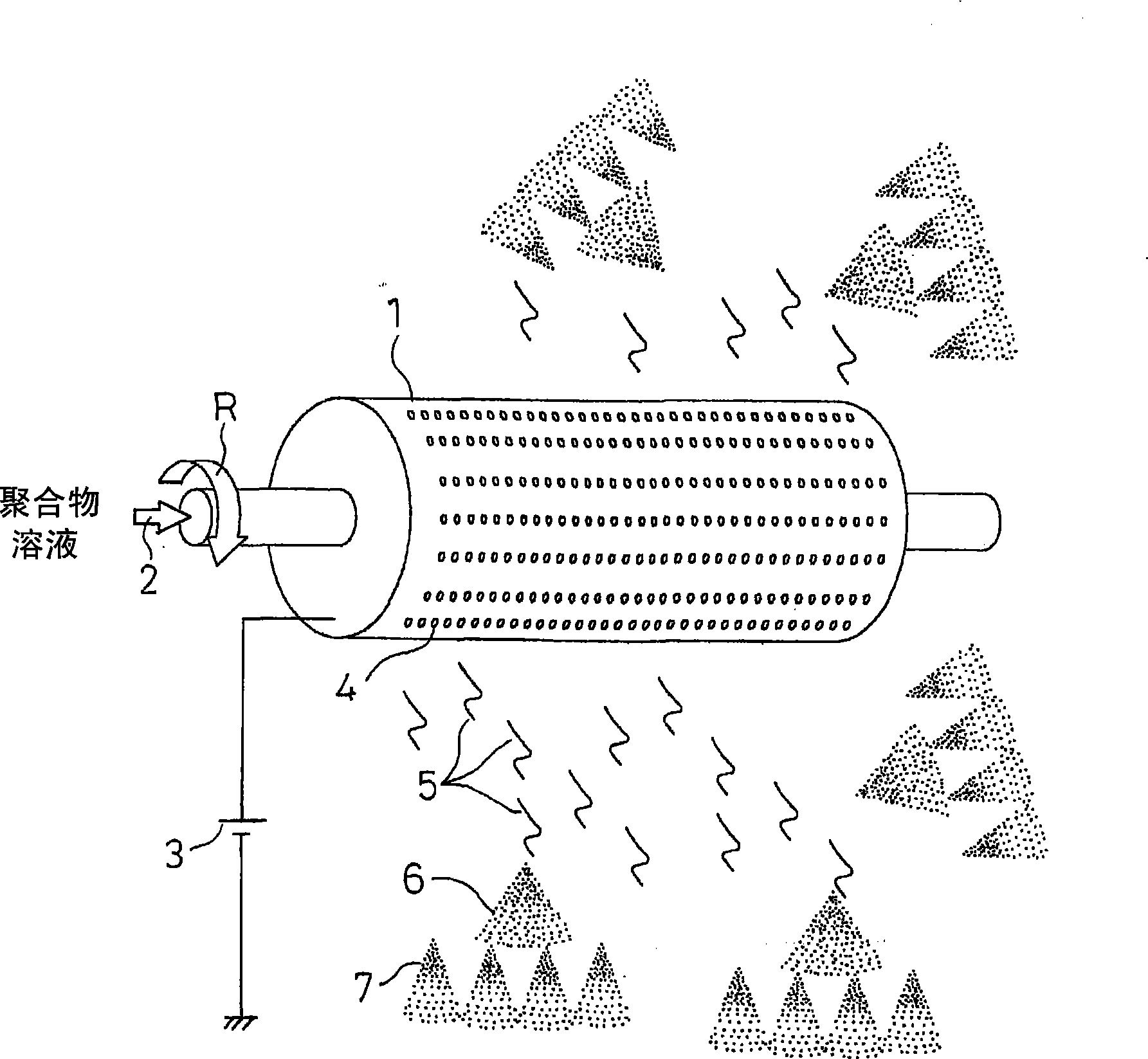
[0057] will be combined with Figure 1-7B Embodiment 1 of a method and apparatus for producing a polymeric network is described. figure 1 is a schematic diagram illustrating the principle of a method of producing nanofibers, which is applied to the method of producing a polymer network of the present embodiment. exist figure 1 Among them, reference numeral 1 denotes a cylindrical container, which is a rotating container with a diameter of 20-500 mm. The rotating container is driven to rotate around the axis of rotation as indicated by arrow R at a rotational speed of 30-6000 rpm. A polymer solution 2 is supplied to a rotating container 1 from one end thereof. In this case, the polymer solution is prepared by dissolving a polymer as a raw material of the nanofibers in a solvent.

[0058] Examples of the polymer forming the polymer solution 2 include polypropylene, polyethylene, polystyrene, polyethylene oxide, polyethylene terephthalate, polybutylene terephthalate, polyet...

Embodiment approach 2

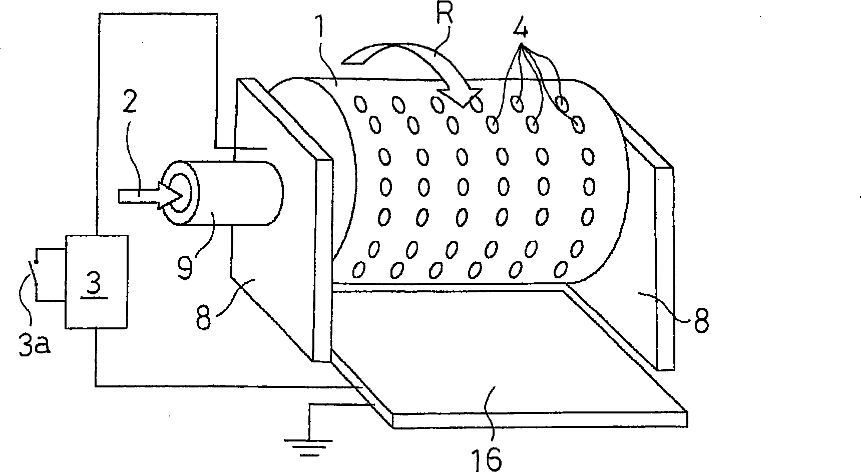
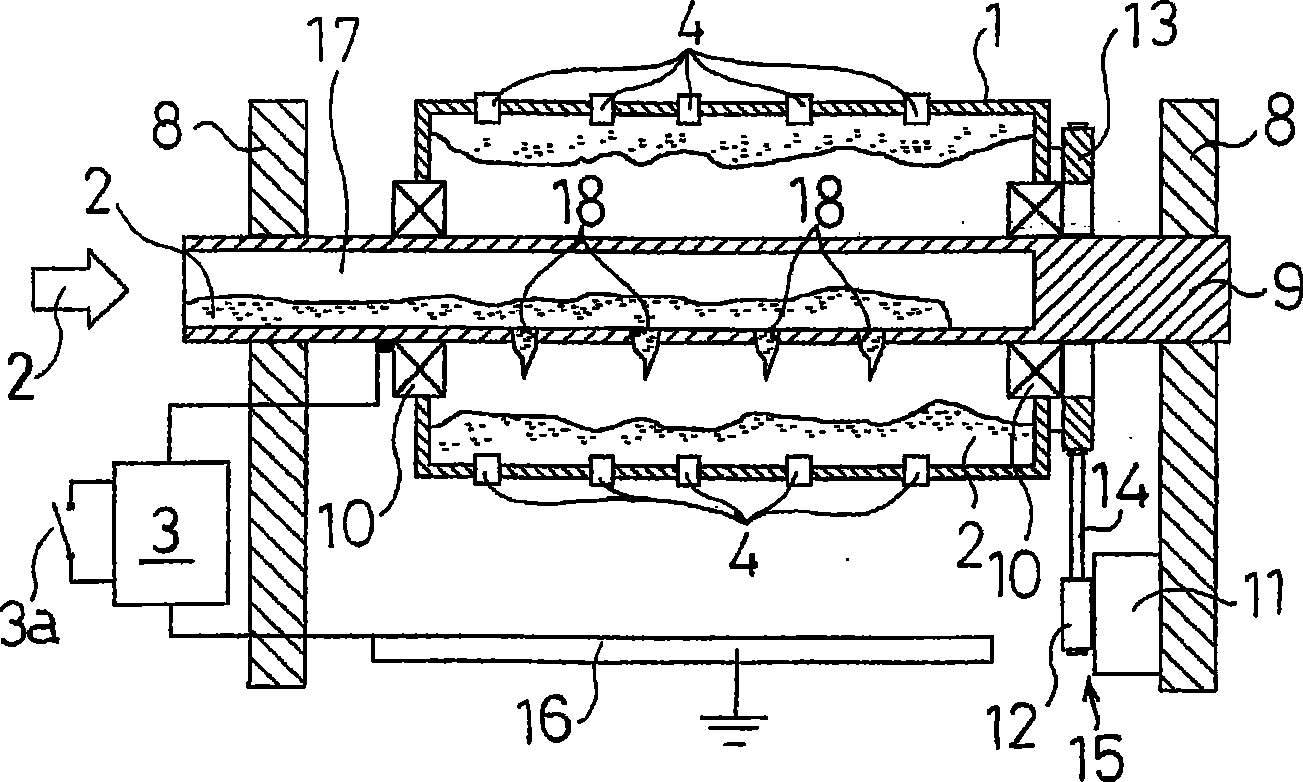
[0072] Next, combine the Figure 8 Embodiment 2 of the method and apparatus for producing a polymer network of the present invention is described. In the description of the following embodiments, the same components appearing in the above embodiments are denoted by the same reference numerals, descriptions of these components are omitted, and only differences are described.

[0073] In the above-mentioned embodiment, an example is described in which the central shaft 9 is fixed on the support member 8 and the cylindrical container 1 is rotatably supported by the bearing 10 around the central shaft 9 . However, in this embodiment, if Figure 8 As shown, the cylindrical container 1 is fixed on the central shaft 9, and the two ends of the central shaft 9 are rotatably supported by the supporting element 8, and the supporting element 8 has a bearing 10 arranged between the supporting element 8 and the central shaft 9. Therefore, the rotary drive 15 is arranged such that the outp...

Embodiment approach 3

[0076] Next, combine the Figure 9 Embodiment 3 of the method and apparatus for producing a polymer network of the present invention is described.

[0077] In the above-mentioned embodiment, an example is described in which the high voltage generated by the high voltage generating device 3 with respect to the ground potential is applied to the cylindrical container 1, and the collector 16 is kept at the ground potential. However, in this embodiment, the positive or negative high voltage generated by the high voltage generator 3 is applied to the collector 16 , and the cylindrical container 1 is grounded through the conductive element 29 and the bearing 10 .

[0078] In this embodiment, the polymer filaments 5 are expelled from a cylindrical container 1 held at a high positive or negative voltage relative to the collector 16 . Then, the polymer solution forming these polymer filaments 5 is charged under the action of the electric field generated between the cylindrical contain...


PUM

PropertyMeasurementUnit
diameteraaaaaaaaaa

Abstract

A polymer solution (2) that is prepared by dissolving a polymeric substance in a solvent is supplied into a cylindrical container (1) serving as a rotating container having a plurality of small holes (4). The cylindrical container (1) is driven to rotate by rotation drive means (15), and an electric field is applied by high voltage generating means (3) to polymeric filaments (5) discharged from the small holes (4) so that they become electrically charged. Then, primary and secondary electrostatic explosions (6, 7) associated with the centrifugal force and the evaporation of the solvent take place, drawing the polymeric filaments and producing nanofibers made of the polymeric substance. These nanofibers are deposited to produce a polymeric web. Accordingly, by employing a simple structure, nanofibers and a polymeric web utilizing them can be produced evenly with excellent productivity.

Description

technical field [0001] The present invention relates to methods and devices for the production of nanofibers made of polymers, as well as highly porous polymeric webs obtained by depositing these nanofibers. Background technique [0002] In general, electrospinning (charge-induced spinning) is a known method for producing nanofibers made of polymers with diameters in the submicron range. In a conventional electrospinning method, a polymer solution is supplied to a needle-shaped nozzle, and a high voltage is applied to the nozzle so that the polymer solution discharged from the nozzle as a filament is charged. As the solvent in the polymer solution evaporates, the distance between these charges decreases and the Coulomb force acting on the solution increases. When this Coulomb force exceeds the surface tension between the filamentous polymer solutions, the filamentous polymer solution undergoes a process called electrostatic detonation, during which the polymer solution is p...

Claims


Application Information

Patent Timeline
Patent Type & Authority Applications(China)
IPC IPC(8): D01D5/00D01D5/18
CPCD01D5/18D01D5/0069B82Y40/00D01D5/00D04H3/16
Inventor 高桥光弘
Owner PANASONIC CORP
Why Eureka
Try Eureka