
Test probe apparatus

A test probe and test pin technology, applied in the direction of measuring devices, measuring electricity, measuring electrical variables, etc., can solve the problems of leaving pits on the printed circuit board, affecting the quality of the printed circuit board, etc., to eliminate contact resistance, The effect of improving accuracy

Active Publication Date: 2009-07-22
JOINT STARS TECH
View PDF0 Cites 11 Cited by
  • Summary
  • Abstract
  • Description
  • Claims
  • Application Information

AI Technical Summary

Problems solved by technology

During the test process, it is easy to leave pits on the printed circuit board, which affects the quality of the printed circuit board.

Method used


Image

  • Test probe apparatus
  • Test probe apparatus
  • Test probe apparatus

Examples


Embodiment 1

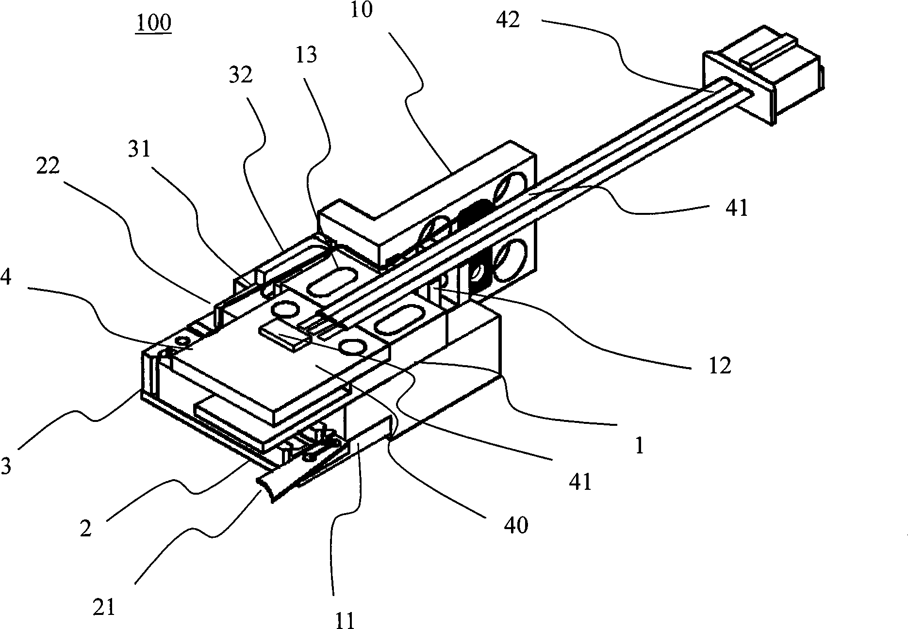
[0025] Such as figure 1 As shown, a test probe device 100 is composed of a needle holder main body 1, a test needle 20, a plastic spring bracket 3 and a pressure sensor 4, wherein the needle holder main body is composed of a fixing seat 10, a test needle fixing seat 11, and a U-shaped pressure adjustment The test needle 2 includes a knife-shaped test probe 21 and a signal output line 22 connected to the test probe. The signal output line 22 is connected to the fixing seat 10 at the rear end of the main body; the test needle 2 is fixed on the On the plastic spring support 3, the plastic spring support 3 is fixed on the front end of the needle seat main body 1 through the test needle holder 11; the pressure sensor 4 includes a pressure sensor main body 40, a pressure data transmission line 41 and a pressure data transmission line connector 42, the pressure sensor main body 40 is fixed on the upper surface of the needle holder main body 1 through the pressure sensor fixing part 1...

Embodiment 2

[0031] The difference between this embodiment and the previous example is:

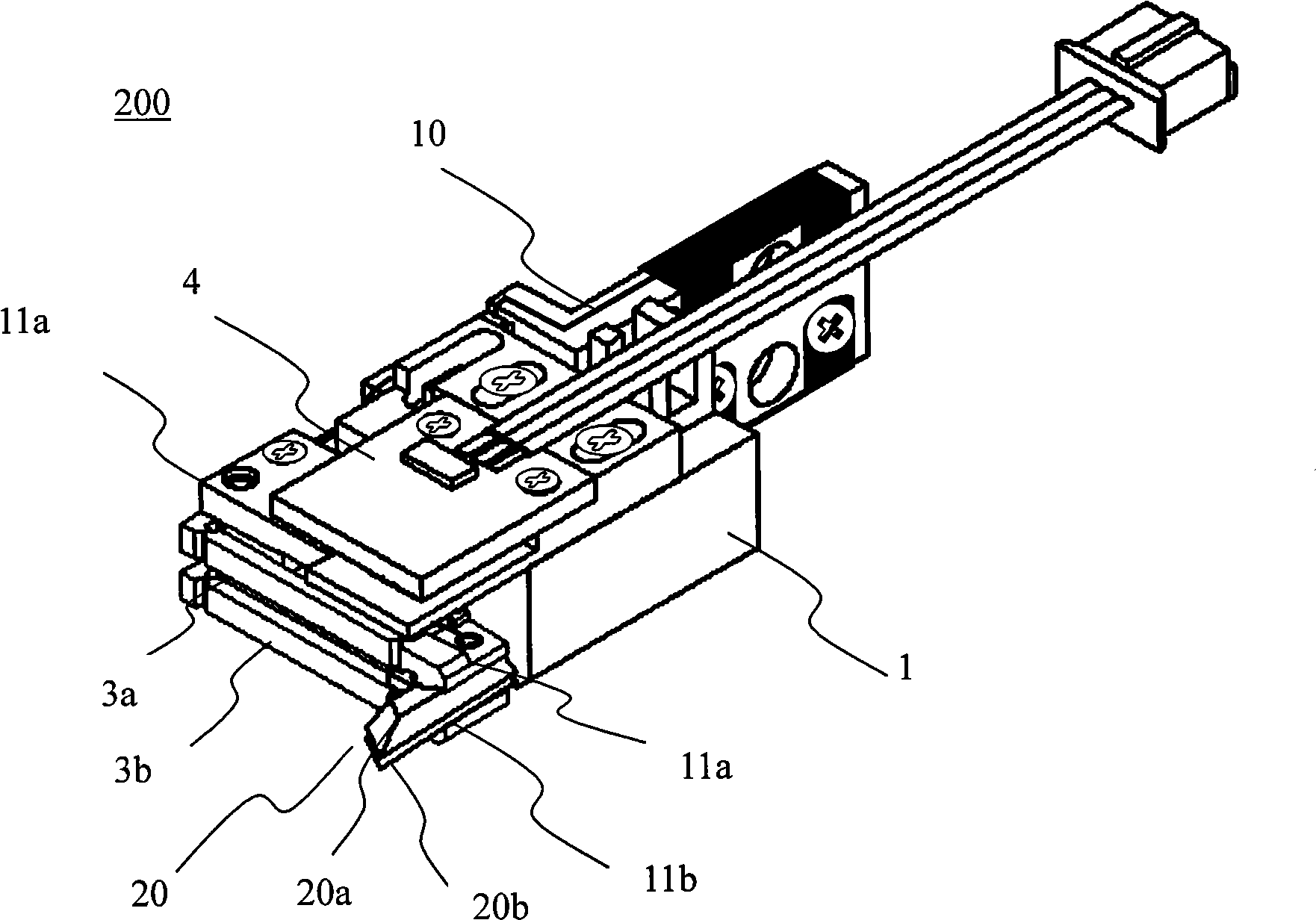
[0032] Such as figure 2 As shown, the test pin 20 includes two parallel upper and lower test pins 20a, 20b, the upper and lower test pins 20a, 20b are knife-type test probe test pins, and the opposite surfaces of the two knife-type test probes 2a, 2b are connected to each other. insulation. The plastic spring support 3a of the upper test needle is fixed on the fixing seat 10 at the front end of the needle holder, and the upper test needle holder 11a combines the plastic spring support 3b of the lower test needle with the plastic spring support 3a of the upper test needle. The signal output lines 22 on the two knife-type test probes 2a, 2b are respectively led to the rear end sampling points of the needle sockets for current and voltage sampling respectively.


PUM

PropertyMeasurementUnit
Thicknessaaaaaaaaaa

Abstract

The invention provides a test probe device comprising a needle bed main body, a test needle, a plastic spring bracket and a pressure sensor, wherein the needle bed main body comprises a fixed seat, a test needle fixer, a U-shaped pressure adjuster and a pressure sensor fixed part; the test needle comprises a knife-type test probe and a signal output line connected with the test probe; the signal output line is connected with the fixed seat at the back end of the main body; the test needle is fixed on the plastic spring bracket, and the plastic spring bracket is fixed at the front end of the needle bed main body; the pressure sensor comprises a pressure sensor main body, a pressure data conducting wire and a pressure data conducting wire connector; the pressure sensor main body is fixed on the upper surface of the needle bed main body via the pressure sensor fixed part; the pressure data conducting wire is connected with the pressure sensor main body and the pressure data conducting wire connector; and light reflected bars are arranged below the induction device of the pressure sensor and at the upper surface of the plastic spring bracket.

Description

technical field [0001] The invention relates to a printed circuit board (PCB) test device, in particular to a test probe device. Background technique [0002] Existing test probe mainly has three parts to form: the one, needle tube: mainly take copper alloy as the gold-plated outside of material. The second is the spring: mainly the piano steel wire and the spring steel are plated with gold. The third is the needle head: mainly tool steel (SK) nickel-plated or gold-plated. The above three parts are assembled into a probe. During the test process, it is easy to leave pits on the printed circuit board, which affects the quality of the printed circuit board. Contents of the invention [0003] The purpose of the present invention is to overcome the shortcomings of the above-mentioned existing test probe devices, and provide a test probe device that can control the pressure of the test points of the printed circuit board and does not leave pits on the printed circuit board. ...

Claims


Application Information

Patent Timeline
IPC IPC(8): G01R1/067G01R1/073
Inventor 覃早才
Owner JOINT STARS TECH
Learn More