Biochip, method for making same, and apparatus applying the biochip

A technology of biochips and biomolecular probes, applied in the field of biochips with characteristic spectrum recognition photosensitive sensor arrays, can solve the problems of inability to obtain real-time information of biological reactions, complicated operation, slow test speed, etc., and achieve real-time monitoring of the reaction process , High detection sensitivity and fast detection speed

Inactive Publication Date: 2009-07-29
邵剑心 +1
View PDF3 Cites 19 Cited by
  • Summary
  • Abstract
  • Description
  • Claims
  • Application Information

AI Technical Summary

Problems solved by technology

The detection sensitivity of this detection method is very high, but the test speed is very slow and the operation is also very complicated
A feasible improvement method is to replace the photomultiplier tube with a CCD camera and irradiate it with a wide-beam laser. This method can increase the detection speed, but the disadvantage is that the detection sensitivity is very low
[0006] exist figure 1 In the detection device using the laser confocal scanning method shown, since a high-sensitivity photomultiplier tube is used, the detection sensitivity can be very high, but the equipment is also very expensive
In addition, because it uses a point-by-point detection method, it takes a long time to measure the entire biochip, and real-time information on biological reactions cannot be obtained.
The advantage of using the CCD camera detection method is that the detection speed is faster, but it requires a more complex imaging system, resulting in a smaller effective aperture
Also, since the fluorescence emission is basically omnidirectional spherical emission, the detection sensitivity of this method is very low
In addition, due to the influence of errors such as aberrations in the imaging optical system, measurement errors such as crosstalk may occur, especially for the detection of high-density gene chips
For the detection of multi-fluorescence spectra, whether the detection device using a photomultiplier tube or a CCD camera needs to replace the optical filter, this will also bring certain errors and limit the acquisition of real-time reaction information.

Method used


Image

  • Biochip, method for making same, and apparatus applying the biochip
  • Biochip, method for making same, and apparatus applying the biochip
  • Biochip, method for making same, and apparatus applying the biochip

Examples


Embodiment Construction

[0021] Exemplary embodiments of the present invention will be described below in conjunction with the accompanying drawings, so as to better understand the purpose, technical solutions and advantages of the present invention. In the description of the present application, the same reference numerals denote the same elements.

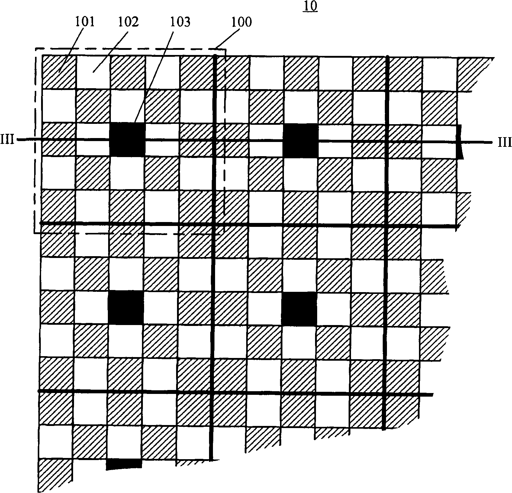
[0022] figure 2 A schematic partial top view of a biochip 10 according to an embodiment of the present invention is shown. In a top view, the biochip 10 can be divided into one or more detection units 100, for example, figure 2 Four complete detection units 100 are shown in the partial top view of . Each detection unit 100 includes a plurality of pixels, and these pixels include at least one detection pixel and at least one reference pixel. In the case where multiple fluorescence characteristic wavelengths need to be detected, multiple groups of detection pixels can be provided, and the optical filters on the surface of each group of detection pixel...


PUM

PropertyMeasurementUnit
thicknessaaaaaaaaaa
wavelengthaaaaaaaaaa

Abstract

The invention discloses a biochip and a preparation method thereof, and a device using the biochip. The biochip comprises at least one detection unit and at least a group of biomolecule probes, and each detection unit comprises at least one detection pixel and at least one reference pixel, and responds to a group of identical biomolecule probes; each detection pixel comprises a semiconductor optical sensor in an arrayed semiconductor optical sensor and an optical filter in an arrayed optical filter, the optical filter totally covers the surface of the semiconductor optical sensor; each reference pixel comprises a semiconductor optical sensor in the arrayed semiconductor optical sensor; each optical filter is provided with a characteristic wavelength so that the wavelength in a predetermined width range with the characteristic wavelength as a center can be transmitted through the optical filter, but the wavelength out of the range can not be transmitted.

Description

technical field [0001] The invention relates to a biochip, in particular to a biochip with a photosensitive sensor array for characteristic spectrum identification. The invention also relates to a preparation method of the biochip and a device using the biochip. Background technique [0002] The prototype of the biochip (biochip) was proposed in the mid-1980s, and it has become one of the core technologies of modern life science research. Biochips include gene chips and protein chips, and are widely used in various fields such as biological research, medical diagnosis, and judicial identification. [0003] The gene chips of the prior art can be mainly divided into three types: 1) nucleic acid probes or cDNA fragments fixed on the surface of polymer substrates (nylon membranes, nitrocellulose membranes, etc.), usually hybridized with isotope-labeled target genes , and detected by radiographic technique; 2) DNA probe array immobilized on glass plate by spotting method, detec...

Claims


Application Information

Patent Timeline
Patent Type & Authority Applications(China)
IPC IPC(8): G01N21/64G01N33/48C12Q1/00
Inventor 樊斌邵剑心
Owner 邵剑心
Why Eureka
Try Eureka