Solar high-temperature vacuum heat-collecting tube

A vacuum heat collecting tube and solar energy technology, which is applied in the field of high temperature vacuum heat collecting tubes and vacuum heat collectors, can solve the problems of high production cost and complex structure of the heat insulation chamber, and achieve the effects of low production cost, simple structure and improved thermal insulation performance

Inactive Publication Date: 2009-08-05
SICHUAN UNIV
View PDF11 Cites 14 Cited by
  • Summary
  • Abstract
  • Description
  • Claims
  • Application Information

AI Technical Summary

Problems solved by technology

The vacuum annular heat insulation chamber can play a role of heat insulation transition to a certain extent, thereby reducing the temperature at the glass nozzle and improving the reliability of the high-temperature vacuum heat collection tube. However, since the vacuum annular heat insulation chamber is still made of metal, Therefore, on the one hand, the "thermal bridge" between the glass tube and the metal tube still exists;

Method used


Image

  • Solar high-temperature vacuum heat-collecting tube
  • Solar high-temperature vacuum heat-collecting tube
  • Solar high-temperature vacuum heat-collecting tube

Examples


Embodiment 1

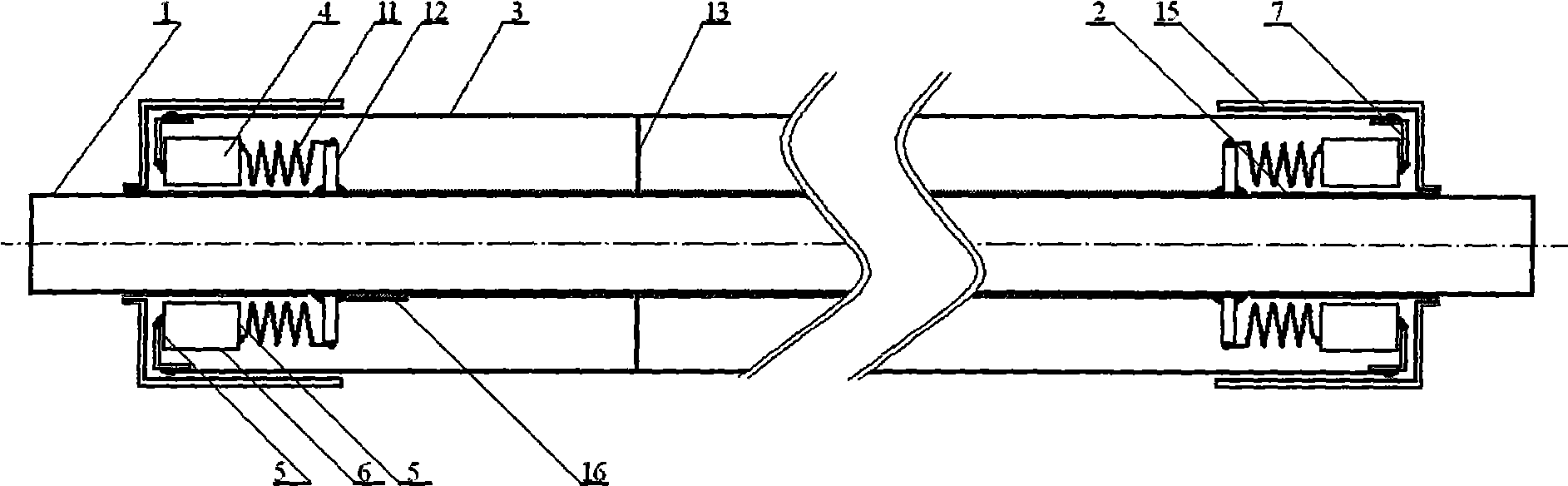
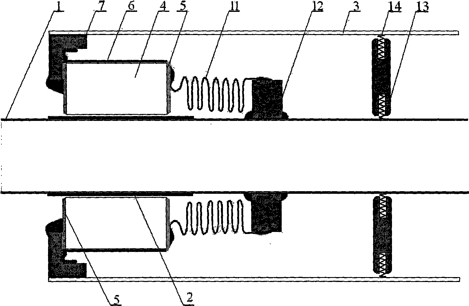
[0034] Such as figure 1 , figure 2 As shown, the high-temperature vacuum-type heat collector provided in this embodiment is mainly composed of a metal inner tube 1, a glass outer tube 3, a ceramic insulation ring 4, a Kovar ring 7, a metal bellows 11, a transition connection plate 12 and a protective end cap 15 poses.

[0035]The metal inner tube 1 is a stainless steel tube coaxially sheathed in the glass outer tube 3, and the outer surface of the steel tube is covered with a black body absorbing coating material which is selective to solar energy. The glass outer tube 3 is made of high boron glass, its inner wall is plated with an anti-reflection film, and the outer wall is plated with an anti-reflection protective film. The glass outer tube 3 and the metal inner tube 1 are hermetically connected, and the interlayer is vacuum. The outer surface of the stainless steel tube 1 in the interlayer is also spot-welded with a vacuum color display band 16 that can absorb air, whic...

Embodiment 2

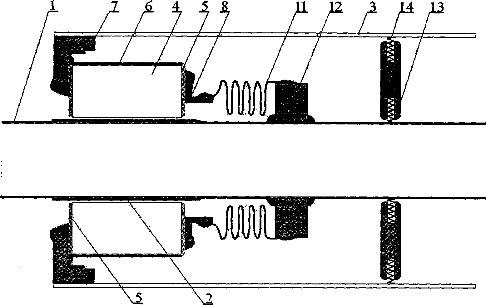
[0039] like image 3 As shown, the high-temperature vacuum type heat collector provided in this embodiment is also mainly composed of a metal inner tube 1, a glass outer tube 3, a ceramic insulation ring 4, Kovar alloy rings 7-8, a metal bellows 11, a transition connection plate 12 and Protective end cap 15 constitutes.

[0040] Due to the structure and production materials of the metal inner tube 1, the glass outer tube 3, the ceramic heat insulating ring 4, the Kovar ring 7, the metal bellows 11, the transition connection plate 12 and the protective end cap 15 of the present embodiment, including the The supporting ring 13 etc. are all the same as in Embodiment 1, so they are omitted. The difference is that a Kovar alloy ring 8 is added between the heat insulating ceramic ring 4 and the metal bellows 11 . The cross section of the Kovar ring 8 is "π"-shaped, and its "π"-shaped upper end surface is welded to the ceramic heat insulating ring 4, and its lower outer surface is ...

Embodiment 3

[0043] As shown in 4, the high-temperature vacuum heat collector provided in this embodiment is also mainly composed of a metal inner tube 1, a glass outer tube 3, a ceramic insulation ring 4, a Kovar alloy ring 9-10, a metal bellows 11, and a transition connection plate 12 and protective end cap 15 constitute.

[0044] Due to the structure and manufacturing materials of the metal inner tube 1, the glass outer tube 3, the ceramic insulation ring 4, the metal bellows 11, the transition land 12 and the protective end cap 15 of the present embodiment, including the supporting ring 13 provided therein, etc. Same as Example 1, so it is omitted. The difference is: ① In this embodiment, a Kovar alloy ring 10 is added between the heat insulating ceramic ring 4 and the metal bellows 11; ② The cross-sectional shape of the Kovar alloy ring 9 connected to the glass outer tube 3 is that On the basis of the concave shape, there is a protrusion extending from the end of the inner ring surfa...


PUM


Abstract

The invention relates to a high-temperature vacuum heat collection pipe for a trough type solar thermoelectric system, comprising a glass outside pipe and a metal inside pipe installed in the glass outside pipe. The glass outside pipe is connected with the metal inside pipe in a sealing way, and the interlayer of the glass outside pipe and the metal inside pipe is in a vacuum state. The high-temperature vacuum heat collection pipe is characterized in that a ceramic insulation ring is arranged between the end of the glass outside pipe and the end of the metal inside pipe. Both end surfaces of the ceramic insulation ring are covered by metallization layers or are respectively provided with an annular groove, the ceramic insulation ring is connected with the glass outside pipe in the sealing way through an alloy component which is connected on or fixedly inlaid in the metallization layer at one end, the other end of the ceramic insulation ring is connected with the metal inside pipe in the sealing way through a transition connecting disk or through the alloy component connected on or fixedly inlaid in the metallization layer and the transition connecting disk. Not only the ceramic insulation ring can eliminate a heat bridge between the glass outside pipe and the metal inside pipe to block heat exchange between the two pipes, and efficiently enhances the working efficiency of the heat collection pipe, but also the invention has simple structure and low manufacture cost, can overcome the manufacture bottleneck of the high-temperature vacuum heat collection pipe for the trough type solar thermoelectric system, and efficiently promotes the development of the solar thermoelectric technology and application thereof.

Description

technical field [0001] The invention belongs to the technical field of solar heat energy utilization devices, and relates to a vacuum heat collector for absorbing solar heat energy, in particular to a high-temperature vacuum heat collection tube used in a trough solar thermoelectric system. Background technique [0002] In solar thermal energy utilization technology, thermal power generation technology can significantly improve the utilization efficiency of solar thermal energy, especially trough solar thermal power generation device, which is considered to be the most practical technology in solar thermal power technology. The trough solar thermal power generation system uses a trough parabolic concentrator to gather sunlight and heat to the heat collecting element located on the focal line of the trough parabolic. The heat collecting element is generally a tubular heat absorber (heat collector) , the fluid working substance inside the tube, after being heated by the conver...

Claims


Application Information

Patent Timeline
Patent Type & Authority Applications(China)
IPC IPC(8): F24J2/48F24J2/51F24J2/46
CPCY02E10/40F24S10/45F24S40/80F24S2025/6013Y02E10/44
Inventor 殷勤俭沙静陈民助贺云峰
Owner SICHUAN UNIV
Why Eureka
Try Eureka