High gain slot array antenna based on left-hand material

A slot array antenna, left-handed material technology, applied to slot antennas, antennas, electrical components, etc., can solve the problems of increased antenna thickness, weight and size, and achieve the effect of simplifying antenna design, easy processing, and simple structure

Inactive Publication Date: 2009-08-12
SICHUAN UNIV
View PDF0 Cites 30 Cited by
  • Summary
  • Abstract
  • Description
  • Claims
  • Application Information

AI Technical Summary

Problems solved by technology

However, in the above antenna, the left-hand material is made as an independent structure and ad...

Method used


Image

  • High gain slot array antenna based on left-hand material
  • High gain slot array antenna based on left-hand material
  • High gain slot array antenna based on left-hand material

Examples


Embodiment

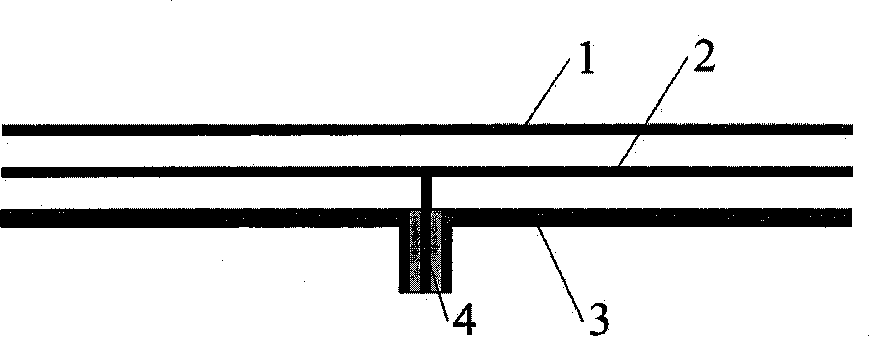
[0023] The structure of the high-gain slot array antenna based on the left-handed material is as follows Figure 1~3 As shown, the antenna is composed of a slot radiation layer 1, a feeding layer 2 and a reflecting layer 3, and is fed with a coaxial connector 4, such as figure 1 shown.

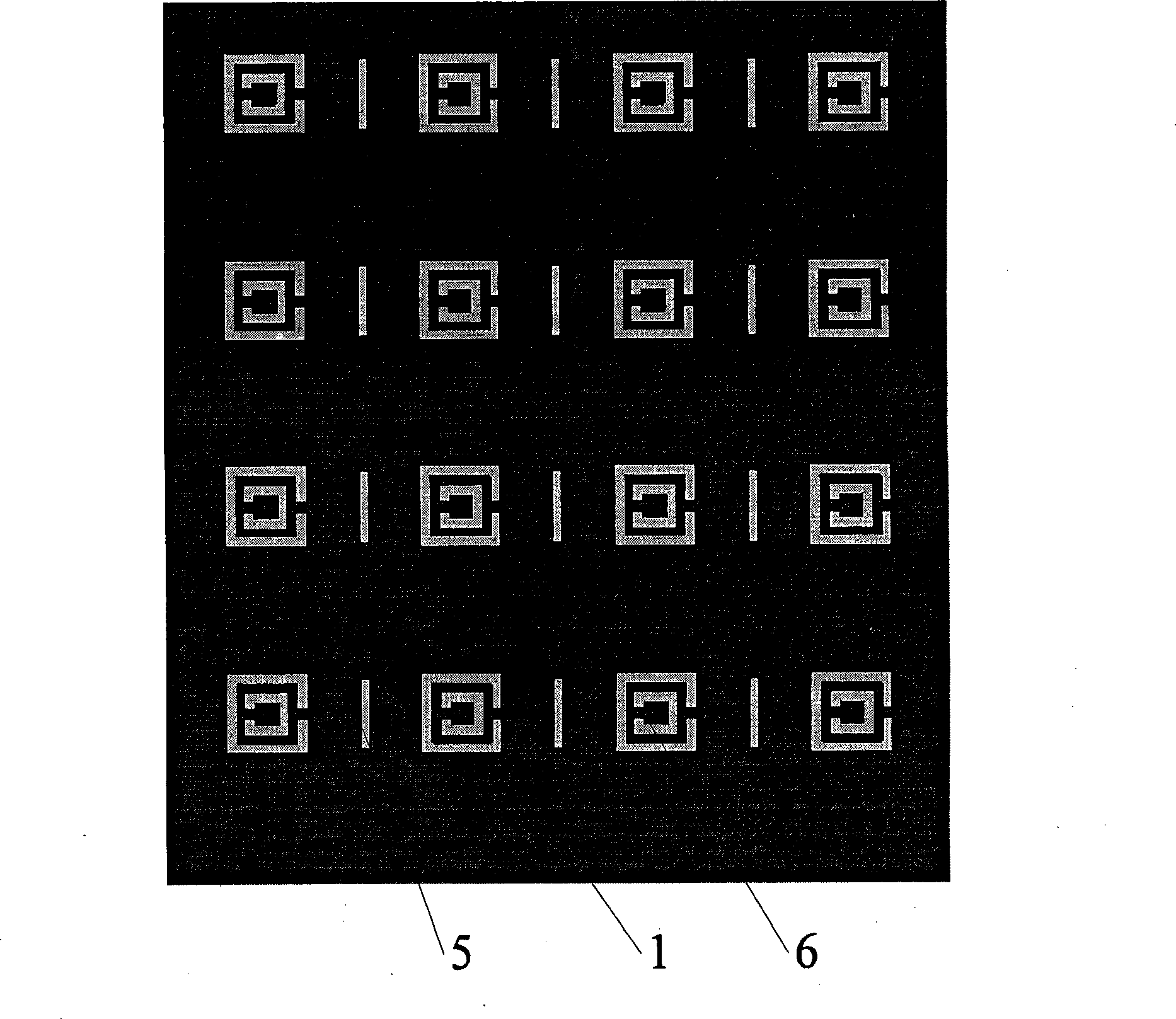
[0024] The slot radiation layer 1 is etched split resonant ring slot array 6 and rectangular narrow strip slot array 5 on metal plate or printed circuit board, such as figure 2 shown.

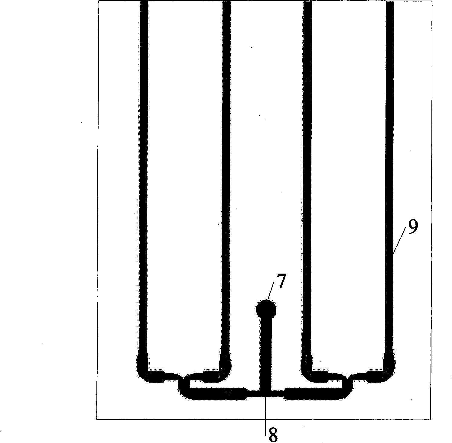
[0025] Both the split resonator ring array and the narrow rectangular bar array are composed of 4×4 16 units, and these slots form a periodic array as the antenna radiation unit. The feed layer 2 includes a T-shaped power subsystem 8 and several metal conduction strips 9. The input port of the T-shaped power subsystem is connected to the inner conductor of the coaxial joint 4 at the feed point 7. Each of the T-shaped power subsystems The output ports are respectively connected to each metal conduction band ...


PUM


Abstract

The invention discloses a high-gain gap array antenna based on a left-handed material, which is characterized in that the antenna has a multilayer structure and comprises three metal layers of a gap radiating layer (1), a feeding layer (2) and a reflecting layer (3); two air layers are formed among three metal layers; a coaxial joint (4) is used for feeding; the gap radiating layer (1) is formed by etching ringent resonant ring gaps (6) and rectangular narrow strip gaps (5) on the metal layer; the gaps form a periodic array as an antenna radiation unit; the feeding layer (2) comprises a T-shaped power splitting system (8) and a plurality of metal conduction bands (9); an input port of the T-shaped power splitting system in a coaxial feeding point (7) is connected with an inner conductor of the coaxial joint (4); each output port of the T-shaped power splitting system is connected with each metal conduction band (9) respectively; the metal conduction band is positioned right below each row of the ringent resonant ring; the gap radiating layer (1) and the reflecting layer (3) act as underground metal; the underground metal and the metal conduction bands (9) form a stripline transmission line. The high-gain gap array antenna has the advantages of high gain, simple manufacture and low cost.

Description

technical field [0001] The invention relates to a high-gain slot array antenna based on left-handed materials, which belongs to the field of antennas in radio equipment. Background technique [0002] High-gain directional antennas are required in many fields such as wireless communication, remote sensing and telemetry, and a large number of high-gain directional antennas have been developed, such as parabolic antennas, angular reflection antennas, and microstrip array antennas. People are constantly developing new types of directional antennas, hoping to achieve high gain while reducing antenna size, processing difficulty and cost, and improving performance indicators such as antenna operating frequency bandwidth and radiation efficiency, so as to meet the requirements of high performance in a large number of engineering applications. gain directional antenna requirements. [0003] Left-handed materials are a research hotspot in international physics and electromagnetism in...

Claims


Application Information

Patent Timeline
IPC IPC(8): H01Q13/08H01Q13/10
Inventor 陈星黄卡玛刘长军郭庆功赵翔华伟闫丽萍杨晓庆
Owner SICHUAN UNIV
Why Eureka
Try Eureka