Three freedom degree plane motor servo controller based on dual-DSP

A technology of servo controller and planar motor, applied in the field of servo controller, can solve problems such as being susceptible to environmental interference, expensive, difficult to determine analog circuit parameters, etc., and achieve the effect of reducing costs

Inactive Publication Date: 2009-08-19
SOUTHEAST UNIV
View PDF1 Cites 10 Cited by
  • Summary
  • Abstract
  • Description
  • Claims
  • Application Information

AI Technical Summary

Problems solved by technology

[0004] Three-degree-of-freedom planar motor control needs to realize large stroke displacement on the X axis, large stroke displacement on the Y axis, and small rotation around the Z axis θ Z For non-contact measurement, foreign positioning platforms often use laser interference ranging system, the resolution reaches nanometer level, and the price is about 60,000 US dollars. For general positioning platform applications, the price is too expensive. The planar motor controller uses 3 sets of laser positions The sensor and the corresponding sensor equation realize the non-contact measurement of the position of three degrees of freedom of motion, the resolution reaches 1 μm, and the price is about 3,000 US dollars; the planar motor controller needs to precisely control the winding current of 12 circuits, and the control system of foreign positioning platforms often uses power The current PI (proportional-integral) control circuit realized by the operational amplifier circuit has the disadvantage that the parameters of the analog circuit are difficult to determine and is susceptible to environmental interference. The current sampling in the planar motor controller is completed by the Hall current sensor, and the power amplification is realized by PWM chopping. The current PI control algorithm is realized by DSP

Method used


Image

  • Three freedom degree plane motor servo controller based on dual-DSP
  • Three freedom degree plane motor servo controller based on dual-DSP
  • Three freedom degree plane motor servo controller based on dual-DSP

Examples


Embodiment Construction

[0036] The present invention will be described in detail below in conjunction with the accompanying drawings.

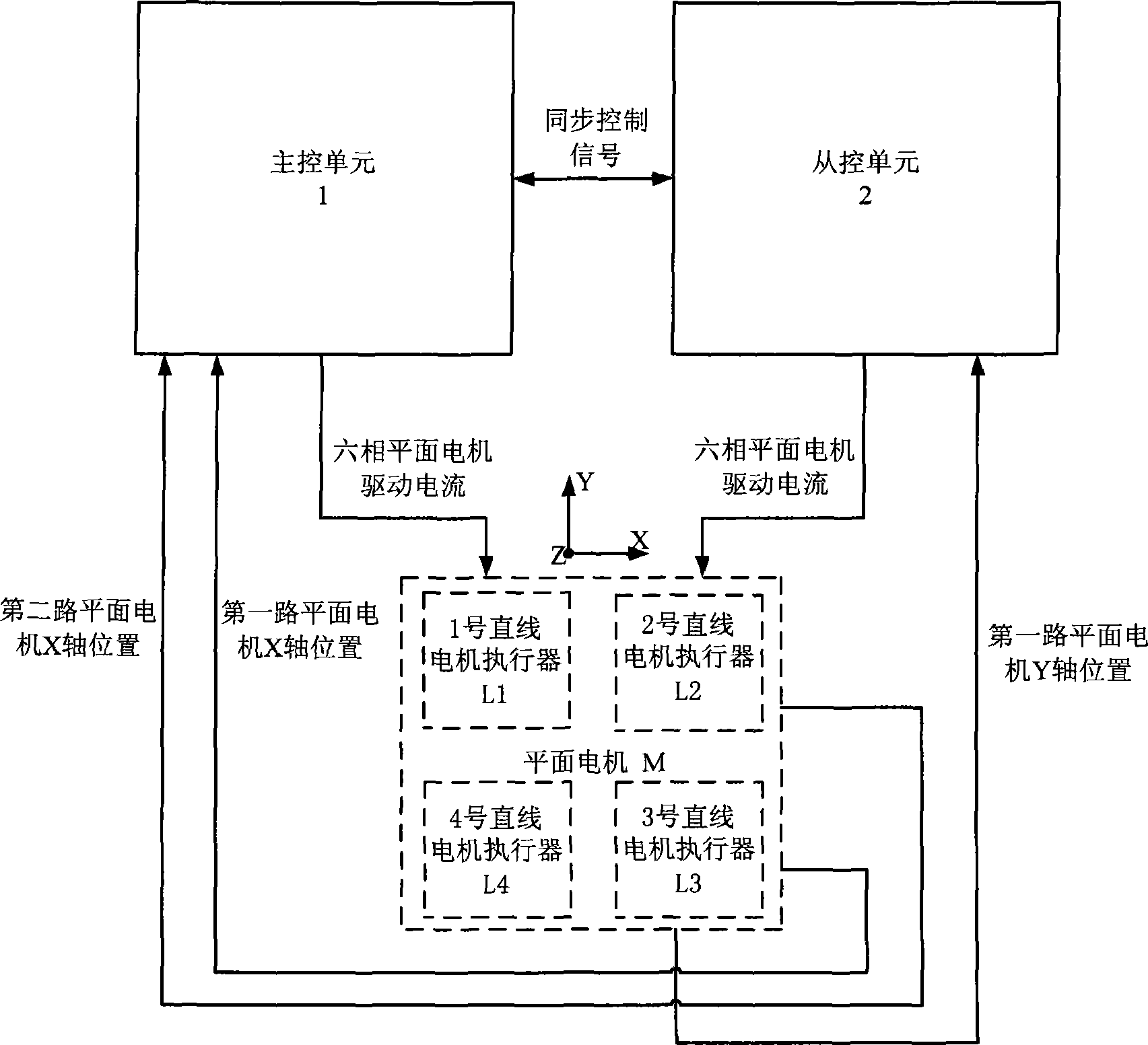
[0037] see figure 1 , a dual-DSP-based 3-DOF planar motor servo controller is characterized in that it includes a master control unit 1 and a slave control unit 2 .

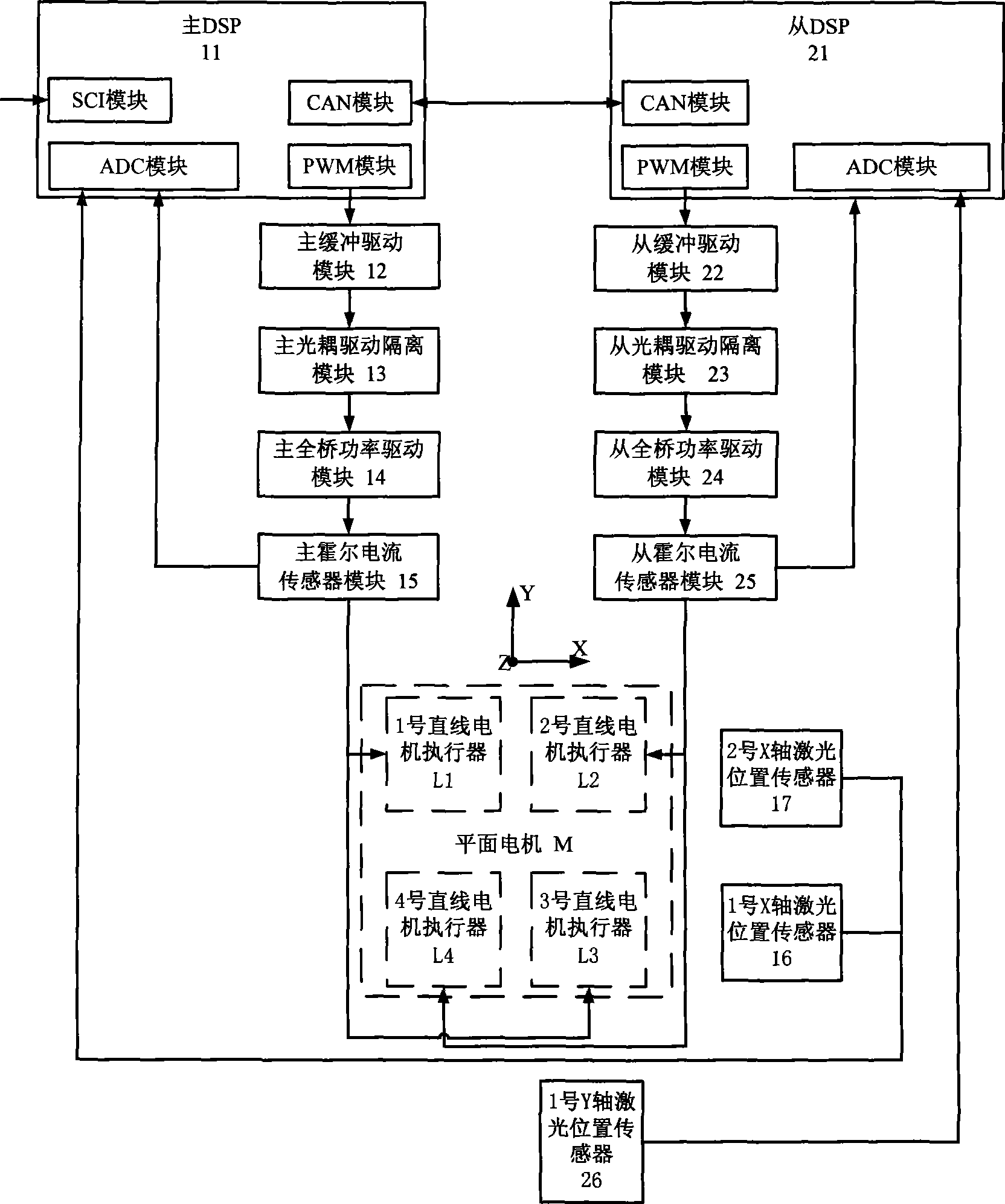
[0038] see figure 2 , the main control unit 1 includes a main DSP11, a main buffer drive module 12, a twelve-way main optocoupler isolation drive module 13, a six-phase main full-bridge power drive module 14, and a six-phase plane for sampling the output of the main control unit The main Hall current sensor module 15 of the motor drive current and the No. 1 X-axis laser position sensor 16 and the No. 2 X-axis laser position sensor 17 for sampling the X-axis positions of the first and second planar motors. The main DSP11 includes the main The ADC module on the DSP chip, the PWM module on the main DSP chip and the CAN module on the main DSP chip; the PWM signal output end of the PWM module on the main...


PUM


Abstract

The invention relates to a servo controller of a dual-DSP-based 3-DOF (degrees of freedom) planar motor. The servo controller comprises a master control unit and a slave control unit, which respectively comprise a DSP chip, an optical coupling driving isolation module, a full-bridge power driving module and a position sensor module. The DSP chip of the master control unit transmits a PWM signal, controls the full-bridge power driving module to output 6-phase planar motor driving current after optical coupling isolation and collects the X-coordinate position of the two-path planar motor by a laser position sensor; the DSP chip of the slave control unit transmits a PWM signal, controls the full-bridge power driving module to output 6-phase planar motor driving current after optical coupling isolation and collects the X-coordinate position of the one-path planar motor by the laser position sensor; the DSP chips of the main control unit and the slave control unit exchange synchronous control signals in real time through a CAN bus and use a 3-DOF synchronous control strategy to control the planar motor to realize fast and accurate positioning of the degree of freedom on X coordinate, Y coordinate and Theta Z.

Description

1. Technical field: [0001] The invention is a servo controller of a 3-degree-of-freedom planar motor. 2. Background technology: [0002] With the rapid development of advanced manufacturing industry, high-precision positioning platform technology has been in-depth research and development, and has broad application prospects in the semiconductor industry, micro-stereolithography, nano-workbench, high-precision plotter and other fields. In addition to the large stroke movement of the horizontal X and Y axes, the high-precision positioning platform often needs to realize small rotations around the coordinate axes, such as the rotation θ around the Z axis Z , the control object 3 degrees of freedom planar motor of the present invention is a kind of can carry out X, Y, θ Z Three-degree-of-freedom fast and precise positioning working platform. [0003] The electromagnetic actuators of the planar motor are 4 sets of 3-phase linear motors. The planar motor controller needs to rea...

Claims


Application Information

Patent Timeline
Patent Type & Authority Applications(China)
IPC IPC(8): H02P21/14H02P25/064
Inventor 黄学良周赣周勤博张前彭晖
Owner SOUTHEAST UNIV
Why Eureka
Try Eureka