Feedforward amplifier and control method thereof

一种反馈放大器、放大器的技术,应用在放大器、改进放大器以提高效率、放大器类型等方向,能够解决不能失真补偿、复杂、不能完全去除主放大器失真分量等问题

Inactive Publication Date: 2009-08-26
NTT DOCOMO INC
View PDF3 Cites 2 Cited by
  • Summary
  • Abstract
  • Description
  • Claims
  • Application Information

AI Technical Summary

Problems solved by technology

But the actual feed-forward amplifier cannot completely remove the distortion component produced by the main amplifier
This is because there is a limit to the adjustment to achieve equal amplitude, anti-phase, and equal delay in the distortion detection circuit and the distortion removal circuit, and in addition, the individual frequency characteristics of the distortion detection circuit and the distortion removal circuit cannot fully cope with the Doherty amplifier. The frequency characteristics of the complex nonlinear characteristics produced by the
In this way, high power efficiency can be achieved in the state of peak amplifier operation, but there is a problem that sufficient distortion compensation cannot be performed due to complex nonlinear characteristics.
Since the out-of-band leakage power limited by the wireless system is below the standard value, even if a Doherty amplifier is used as the main amplifier, an output compensation (back off) of about 5dB is required, and power efficiency cannot be improved.

Method used


Image

  • Feedforward amplifier and control method thereof
  • Feedforward amplifier and control method thereof
  • Feedforward amplifier and control method thereof

Examples


no. 1 Embodiment

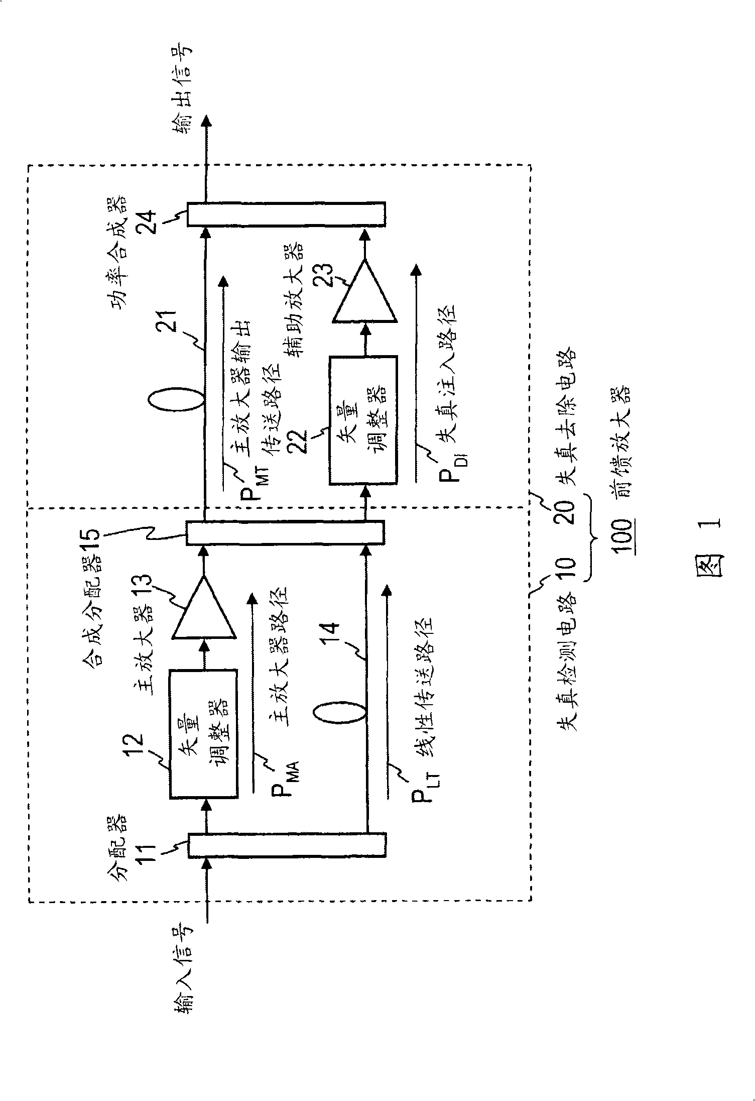
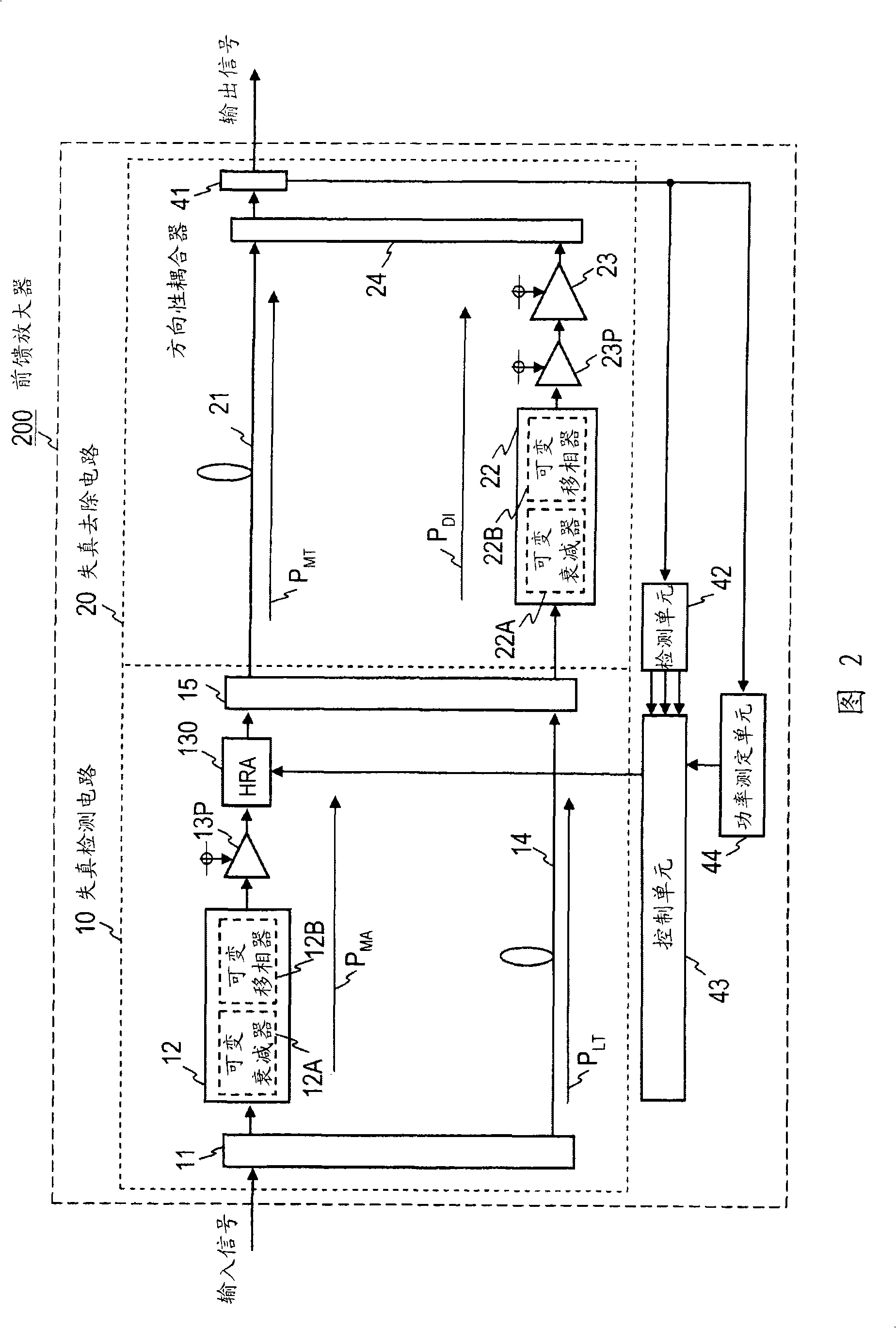
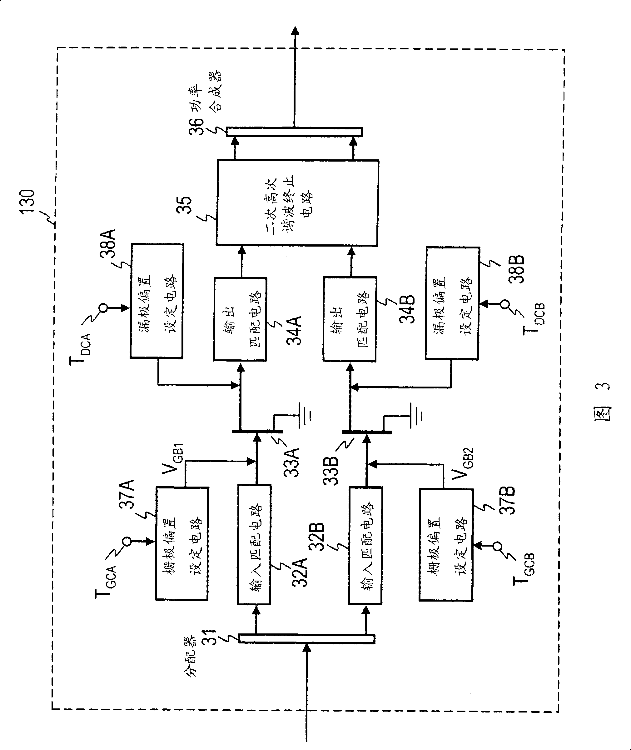
[0061] figure 2 A feedforward amplifier 200 according to the first embodiment of the present invention is shown. For and such figure 1 The structural elements of the feedforward amplifier 200 corresponding to the structural elements of the conventional feedforward amplifier 100 shown are added with the figure 1 Like reference numerals are shown. One of the characteristics of the feedforward amplifier 200 is that a harmonic feedback amplifier (Harmonic Reaction Amplifier: HRA) 130 is used as the main amplifier, and the operating point of the HRA 130 is controlled so as to maximize the power efficiency of the feedforward amplifier 200 . For this control, the following components are provided: a directional coupler 41 that extracts a part of the output of the feedforward amplifier 200; a detection unit 42 that detects a main wave component and an out-of-band component contained in the extracted signal; The output power of amplifier 200 and the power measurement unit 44 of the...

no. 2 Embodiment

[0085] An example in which the power efficiency of the feedforward amplifier is further improved after the control of the gate bias voltage and the drain bias voltage of the HRA 130 in the first embodiment is shown. Figure 9 A feedforward amplifier 300 as a second embodiment is shown. The feedforward amplifier 300 is different from the aforementioned feedforward amplifier 200. In order to adjust the vector adjusters 12 and 22 of the distortion detection circuit 10 and the distortion removal circuit 20, the feedforward amplifier 300 has the following structure: DI A directional coupler 45 is provided on the input side of the vector adjuster 22 , and a switch 46 selects the signals from the directional couplers 41 and 45 and supplies them to the detection unit 42 .

[0086] The control unit 43 controls the variable attenuator 12A and the variable phase shifter 12B of the distortion detection circuit 10 and the variable attenuator 22A and the variable phase shifter 22B of the di...

no. 3 Embodiment

[0093] exist Figure 11 The feedforward amplifier 400 shown has the advantage of using a pilot signal at Figure 9 In the feedforward amplifier 300 shown, adjustment control of the vector adjusters 12 and 22 of the distortion detection circuit 10 and the distortion removal circuit 20 is performed. The feedforward amplifier 400 is based on the structure of the feedforward amplifier 300, and further includes: a directional coupler 8 provided on the input side of the distributor 11, a directional coupler 17 provided between the preamplifier 13P and the HRA130, a second A pilot signal generator 9 and a second pilot signal generator 18 . The first pilot signal generator generates the first pilot signal S of the CW2 wave with a frequency interval of about 1kHz at a center frequency sufficiently far from the main wave component P1 . Among them, the first pilot signal S P1 The center frequency of is set to the same frequency band as the main wave component. The second pilot signa...


PUM


Abstract

In a feedforward amplifier including a signal cancellation circuit (10) and a distortion eliminating circuit (20), a harmonic reaction amplifier (130) is used as a main amplifier of the signal cancellation circuit. A controller (43) obtains an adjacent channel leakage power ratio (ACLR) and a power efficiency from an output of the feedforward amplifier (200) and controls the gate bias voltages of two transistors (33A and 33B) of the harmonic reaction amplifier (130) to maximize the power efficiency under the condition that the ACLR is less than or equal to a reference value.

Description

technical field [0001] The present invention relates to a high-efficiency feedforward amplifier and its control method. Background technique [0002] In recent years, in order to secure a service area accompanying the rapid spread of mobile communications, it is necessary to install a plurality of base station devices. Depending on the installation of the base station device, it is also necessary to install a plurality of base station devices at the same location. In addition, it is also necessary to reduce the power consumption of the base station apparatus. Based on such a background, miniaturization and power saving of base station devices are required. Devices for base stations generally include modulation and demodulation devices, transmission amplifiers, radiators, various control devices, and the like. Since most of the power consumption of the base station apparatus is occupied by the transmission amplifier, attention has been paid to saving power of the transmiss...

Claims


Application Information

Patent Timeline
Patent Type & Authority Applications(China)
IPC IPC(8): H03F1/32H03F1/02H03F3/60
CPCH03F1/0261H03F2200/18H03F3/24H03F1/3229H03F2200/451H03F1/32H03F1/02
Inventor 铃木恭宜楢桥祥一
Owner NTT DOCOMO INC
Why Eureka
Try Eureka