
Method for generating high-frequency ultrasonic waves based on dielectric body superlattice

A high-frequency ultrasonic and super-lattice technology, which is applied in the direction of sound-generating devices, fluids that use vibration, and instruments, can solve problems such as ineffective separation, and achieve convenient multi-frequency and multi-directional ultrasonic output, easy impedance matching, and simple structure. Effect

Active Publication Date: 2009-09-02
NANJING UNIV
View PDF1 Cites 1 Cited by
  • Summary
  • Abstract
  • Description
  • Claims
  • Application Information

AI Technical Summary

Problems solved by technology

Since the direction of the reciprocal vector determines the direction of sound wave transmission, although the one-dimensional superlattice can simultaneously excite multiple frequencies or realize broadband ultrasonic waves, the ultrasonic waves of different frequencies propagate in the same direction at the same time and cannot be effectively separated.

Method used

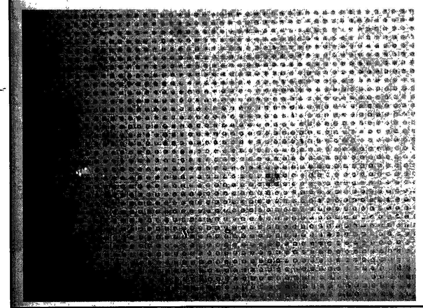

Image

  • Method for generating high-frequency ultrasonic waves based on dielectric body superlattice
  • Method for generating high-frequency ultrasonic waves based on dielectric body superlattice
  • Method for generating high-frequency ultrasonic waves based on dielectric body superlattice

Examples


Embodiment 1

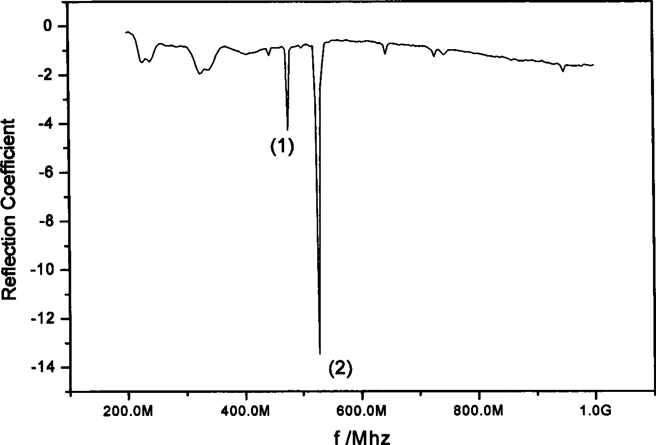
[0031] Fabrication of electroacoustic transducing media using tetragonal structural acoustic superlattice (cutting LiTaO in the z direction 3 example). A layer of uniform gold or silver electrodes is prepared respectively on the upper and lower x-y surfaces of the crystal by coating, vapor deposition or ion sputtering. Connect to the network analyzer, measure the reflection coefficient of the sample under the z-direction alternating electric field (this coefficient is related to the resonance frequency), follow the instructions attached Figure 4 , to get a series of reflection peaks, the appearance of each peak corresponds to a reciprocal lattice vector of a specification, the reflection intensity can represent the resonance intensity, and the frequency is the frequency of the excited ultrasonic wave.

Embodiment 2

[0033] Fabrication of electroacoustic transducing media using tetragonal structural acoustic superlattice (cutting LiTaO in the z direction 3 example). The difference from Example 1 is that a layer of uniform gold or silver electrodes is prepared on two opposite y-z surfaces of the crystal by coating, vapor deposition or ion sputtering respectively. Connect to the network analyzer, measure the reflection coefficient of the sample under the x-direction alternating electric field (this coefficient is related to the resonance frequency), follow the instructions attached figure 2 , it can be observed that the ultrasonic waves excited by the x-direction reciprocal lattice vector have the greatest intensity under the x-direction electric field.

Embodiment 3

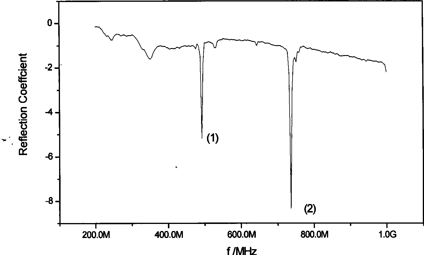
[0035] Fabrication of electroacoustic transducing media using tetragonal structural acoustic superlattice (cutting LiTaO in the z direction 3example). The difference from examples 1 and 2 is that a layer of uniform gold or silver electrodes is prepared on two opposite x-z surfaces of the crystal by coating, evaporation or ion sputtering respectively. Connect to the network analyzer, measure the reflection coefficient of the sample under the y-direction alternating electric field (this coefficient is related to the resonance frequency), follow the instructions attached image 3 , it can be observed that the ultrasonic waves excited by the reciprocal lattice vector in the y direction have the greatest intensity under the alternating electric field in the y direction.


PUM


Abstract

The invention discloses a method for generating high-frequency ultrasonic waves based on a dielectric body superlattice and belongs to the field of electroacoustic energy transduction. The superlattice takes a piezoelectric crystal as a medium. An arranged two-dimension modulating structure provides a plurality of reciprocal lattice vectors at the same time and can realize multidirectional multi-frequency and multimode ultrasound output at high frequency in an alternative electric field, wherein the ultrasonic waves at different frequency have different propagation directions and can be used independently. The frequency, propagation direction and sound wave mode of high-frequency ultrasonic waves generated by the method can be designed and modulated by the two-dimension structure periodically and symmetrically. The method has the advantages of simplicity, high efficiency and integration.

Description

technical field [0001] The invention relates to a method for generating high-frequency ultrasonic waves, in particular to a method for generating high-frequency ultrasonic waves based on a dielectric body superlattice. Background technique [0002] In August 1992, Zhu Yong, Min Naiben and others from Nanjing University Solid Microstructure Laboratory published "Ultrasonic excitation and propagation in the acoustic superlattice" on J.Appl.Phy. (Journal of Applied Physics). in an acoustic superlattice)", reporting a one-dimensional fixed periodic structure LiNbO 3 Various ultrasonic excitation and transmission modes in the superlattice, and studied the impedance characteristics and electromechanical coupling coefficients in various modes. The superlattice preparation method at that time was the eccentric rotation pulling method, and the preparation period was a fixed period, ranging from 7 microns to 14 microns. [0003] In August 1993, Min Naiben, Chen Yanfeng and others ap...

Claims


Application Information

Patent Timeline
IPC IPC(8): G10K9/12B06B1/02G10K9/122B06B1/06
Inventor 尹若成何程陈延峰卢明辉陆延青祝世宁朱永元闵乃本
Owner NANJING UNIV
Learn More