A method for rapid generation and control of conductive polyvinylidene fluoride conductive layers
A polyvinylidene fluoride and conductive layer technology, applied in the field of conductive polymer preparation and laser micromachining, can solve the problems of artificial control of non-conductive areas, rapid preparation of conductive layer obstacles, upper limit of laser energy density, etc., to avoid time-consuming and energy, fast preparation speed and high degree of automation
- Summary
- Abstract
- Description
- Claims
- Application Information
AI Technical Summary
Problems solved by technology
Method used
Image
Examples
Embodiment 1
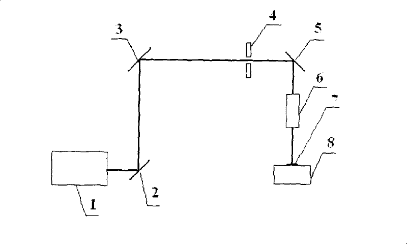
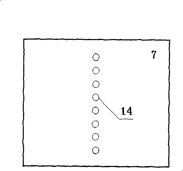
[0045] First, in the attached figure 1 In the shown excimer laser mask direct writing optical path system, a circular mask with a diameter of 4mm is selected, and microgrooves are constructed on the surface 7 of the PVDF film. The diameter of the microgrooves is 0.26mm, and the distance between each microgroove is 1cm. Etching 8 microgrooves arranged in a straight line 14, as attached image 3 shown. During the experiment, the energy of laser 1 was 200mJ, the repetition frequency was 4Hz, and each microhole was etched with 30 pulses. Then, the He-Ne laser is used for positioning, the three-dimensional workbench 8 is turned on, the laser 1 is turned on, and the texture of the micro-pattern is automatically completed through the laser control software and the three-dimensional workbench control software.
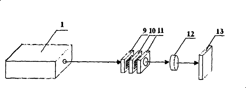
[0046] The textured sample is placed on the workbench 13 of the excimer laser irradiation optical system, collimated by the He-Ne laser, and the optical path is adjusted so ...
Embodiment 2
[0048] First, in the attached figure 1 In the shown excimer laser mask direct writing optical path system, a circular mask with a diameter of 4mm is selected, and microgrooves are constructed on the surface 7 of the PVDF film. The diameter of the microgrooves is 0.26mm, and the distance between two adjacent microgrooves is 1cm. Graphics, continuous etching three rows and three columns of 9 equally spaced microgrooves 15, as attached Figure 4 shown. During the experiment, the energy of laser 1 was 300mJ, the repetition frequency was 4Hz, and each microhole was etched with 30 pulses. Then, the He-Ne laser is used for positioning, the three-dimensional workbench is turned on, the laser is turned on, and the texture of the micro-pattern is automatically completed through the laser control software and the three-dimensional workbench control software. Turn off the laser and turn off the 3D workbench.
[0049] The textured sample is placed on the workbench 13 of the excimer lase...
Embodiment 3
[0051] First, in the attached figure 1 In the excimer laser mask direct writing optical system shown, a circular mask with a diameter of 4 mm is selected. During the experiment, the energy of laser 1 is 400 mJ, the repetition frequency is 4 Hz, and the table speed is 10 mm / min. Structure microgroove on PVDF film surface 7, width is 0.26mm, and length is the microchannel 16 of 8cm, as attached Figure 5 shown. Then, the He-Ne laser is used for positioning, the three-dimensional workbench is turned on, the laser is turned on, and the texture of the micro-pattern is automatically completed through the laser control software and the three-dimensional workbench control software. Turn off the laser and turn off the 3D workbench.
[0052] The textured sample is placed on the workbench 13 of the excimer laser irradiation optical system, collimated by the He-Ne laser, and the optical path is adjusted so that it has a complete spot shape. Set the output energy of the laser to 300mJ, ...
PUM
| Property | Measurement | Unit |
|---|---|---|
| width | aaaaa | aaaaa |
| width | aaaaa | aaaaa |
Abstract
Description
Claims
Application Information
 - R&D
- Intellectual Property
- Life Sciences
- Materials
- Tech Scout
- Unparalleled Data Quality
- Higher Quality Content
- 60% Fewer Hallucinations
Browse by: Latest US Patents, China's latest patents, Technical Efficacy Thesaurus, Application Domain, Technology Topic, Popular Technical Reports.
© 2025 PatSnap. All rights reserved.Legal|Privacy policy|Modern Slavery Act Transparency Statement|Sitemap|About US| Contact US: help@patsnap.com


