Method for processing composite shot blasting considering both surface peening and polishing

A technology of shot peening and surface strengthening, which is applied in the field of composite shot peening that takes both surface strengthening and polishing into consideration, can solve the problems of increased surface roughness, small decline, and complicated process operations, and achieves high production efficiency and high work efficiency. The effect of mature principle and simple process operation

Inactive Publication Date: 2009-09-16
SHANGHAI JIAO TONG UNIV
View PDF0 Cites 29 Cited by
  • Summary
  • Abstract
  • Description
  • Claims
  • Application Information

AI Technical Summary

Problems solved by technology

People such as C.A.Rodopoulos in "International Journal of Fatigue (International Journal of Fatigue)" (2004, the 26th volume, 849-856 page) published " 2024-T351 aluminum alloy controlled shot-peening fatigue resistance optimization - method, result "Optimization of the fatigue resistance of 2024-T351aluminum alloys by controlled shot peening-methodology, results and analysis" paper, studied the impact of shot peening on the surface microhardness of metal materials, and found that under single shot peening conditions, shot peening There is a limit to the improvement of the microhardness of the pellet deformed layer
In the paper "Analysis of the Roughness of Pure Titanium High Energy Shot Peening Surface Nanoization" published in "China Surface Enginee

Method used


Image

  • Method for processing composite shot blasting considering both surface peening and polishing
  • Method for processing composite shot blasting considering both surface peening and polishing
  • Method for processing composite shot blasting considering both surface peening and polishing

Examples


Embodiment 1

[0018] The experimental material of this embodiment: Inconel750 nickel base alloy, shot peening sample size 70 × 20 × 20mm 3 , numbered 1.

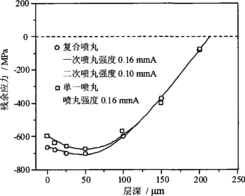
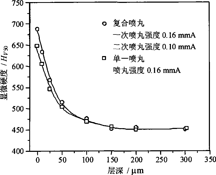
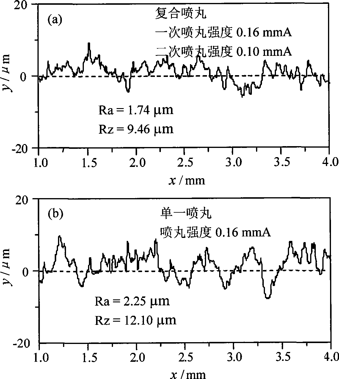
[0019] During implementation, a pneumatic shot blasting machine is used for compound shot peening. Firstly, the No. 1 sample is shot peened once, the shot peening conditions are air pressure 0.4MPa, shot peening intensity 0.16mmA. Then perform secondary shot peening on the basis of the primary shot peening, the shot peening conditions are air pressure 0.3MPa, shot peening intensity 0.10mmA. The projectiles used in the primary shot peening and the secondary shot peening are exactly the same, all of which are stainless steel projectiles with a diameter of 0.3 mm.

Embodiment 2

[0026] The experimental material of this example: 6351Al alloy, the size of shot peening sample is 70×20×20mm 3 , No. 3.

[0027] During implementation, a pneumatic shot blasting machine is used for compound shot peening. Firstly, the No. 3 sample is shot peened once, the shot peening conditions are air pressure 0.6MPa, and shot peening intensity 0.25mmA. Then perform secondary shot peening on the basis of the primary shot peening, the shot peening conditions are air pressure 0.4MPa, shot peening intensity 0.15mmA. The projectiles used in the primary shot peening and the secondary shot peening are exactly the same, all of which are ceramic projectiles with a diameter of 0.2 mm.

[0028] comparative example

[0029] As a comparison, the sample with the same material and sample size as No. 3 sample was selected for single shot peening, numbered No. 4, and the shot peening equipment and shot peening conditions were exactly the same as the single shot peening in compound shot p...


PUM

PropertyMeasurementUnit
Diameteraaaaaaaaaa

Abstract

The invention relates to a method for processing a composite shot blasting considering both surface peening and polishing. The method comprises the following: a first step, carrying out primary shot blasting on a material to reach saturated shot blasting intensity; carrying out secondary shot blasting based on primary shot blasting; wherein, the saturated shot blasting intensity of secondary shot blasting is about 0.6 time that of the primary shot blasting and shot blasting equipment and used shots are the same as the shot blasting equipment and used shots of the primary shot blasting. The method increases stress of residual pressure on the surface and near surface area without changing the shot blasting equipment and shots, thereby improving the microhardness of the surface and the near surface area, significantly reducing surface roughness of parts, and improving the surface quality of the shot blasting material.

Description

technical field [0001] The invention relates to a shot peening method in the technical field of surface treatment, specifically, a composite shot peening treatment method that takes both surface strengthening and polishing into account. Background technique [0002] Surface shot peening technology is a key manufacturing process to improve the fatigue life and stress corrosion resistance of mechanical parts. Shot peening factors include two aspects, namely residual stress strengthening and organizational strengthening. Tissue strengthening can effectively prevent crack initiation, while residual stress strengthening can prevent crack propagation. Controlling these two factors can change the surface properties of components. The changes of the surface layer of the material caused by shot peening include: 1) the introduction of residual compressive stress field, 2) the optimization of the deformed structure and the increase of microhardness, and 3) the change of surface rough...

Claims


Application Information

Patent Timeline
IPC IPC(8): B24C1/08B24C1/10
Inventor 姜传海栾卫志余震
Owner SHANGHAI JIAO TONG UNIV
Why Eureka
Try Eureka