Room temperature plasma torch array device for simultaneous fiber modification and sewage treatment

A plasma torch and sewage treatment technology, which is applied in fiber treatment, illuminated water/sewage treatment, oxidized water/sewage treatment, etc., can solve the problems of burnt materials, small area of ​​plasma torch, and easy cracking of the medium layer, and achieve The effect of prolonging the working life, avoiding medium rupture, and accelerating the degradation rate

Inactive Publication Date: 2011-12-21
ZHEJIANG SCI-TECH UNIV
View PDF0 Cites 0 Cited by
  • Summary
  • Abstract
  • Description
  • Claims
  • Application Information

AI Technical Summary

Problems solved by technology

However, the external electrodes of these discharge systems are all metal, and are covered or plated on the surface of the dielectric layer. Due to the difference in expansion coefficient between the dielectric layer and the metal, the dielectric layer is easily broken or the metal layer falls off during the discharge process. On the other hand, using this When the torch is used to process irregular materials, such as for the modification of the inner surface of the tube, the reflected plasma will short-circuit the two electrodes and generate a very hot plasma arc, which will burn the modified materials, especially organic materials.
Although some researchers use casing-type tap water as electrodes, the area of ​​the plasma torch is too small to make a difference in industry.
In particular, the atmospheric pressure glow plasma torch is used for fiber modification, the efficiency is relatively low, and the ultraviolet rays and ozone produced will cause certain harm to people and the environment

Method used


Image

  • Room temperature plasma torch array device for simultaneous fiber modification and sewage treatment
  • Room temperature plasma torch array device for simultaneous fiber modification and sewage treatment

Examples


Embodiment Construction

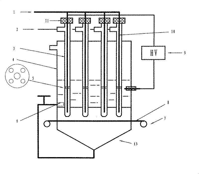
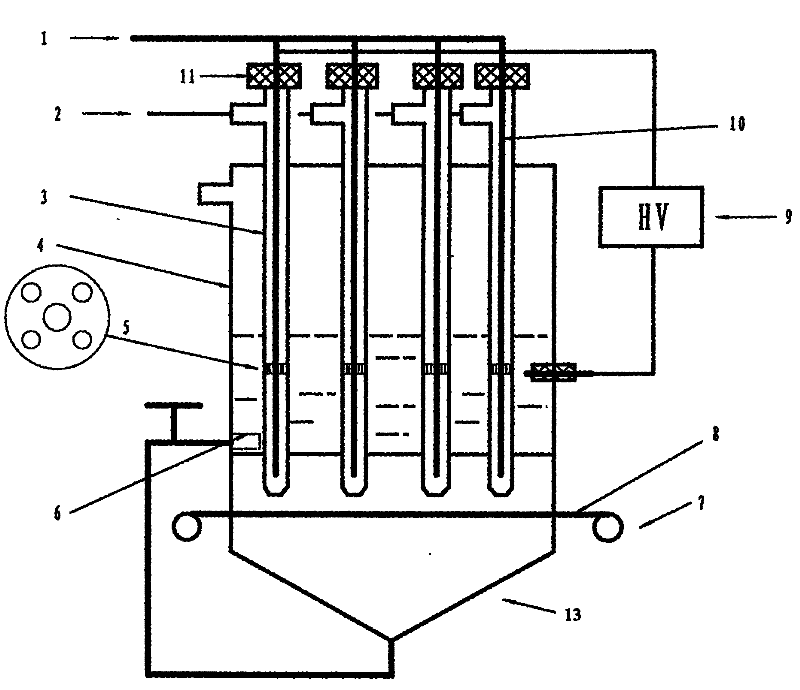
[0013] The present invention will be further described below in conjunction with the accompanying drawings and embodiments.

[0014] As shown in the accompanying drawings, the present invention contains a conductive aqueous solution electrode in a plexiglass tank 4, a plurality of rows of quartz tubes 3 with built-in tubular metal electrodes 10 are inserted into the conductive aqueous solution electrode, and one end of the quartz tube 3 passes through the plexiglass tank 4 The bottom enters the modification chamber 13, and the other end of the quartz tube 3 exposes the plexiglass water tank 4 and is sealed with a polytetrafluoroethylene sleeve 11. The tubular metal electrode 10 passes through the polytetrafluoroethylene sleeve 11 to communicate with the active gas source 1. Connected with the inert gas source 2, the bottom of one end of the quartz tube 3 is tapered and has a through hole, and the modification chamber 13 is equipped with fiber filaments 8 corresponding to the nu...


PUM


Abstract

The invention discloses a room temperature plasma torch array device for simultaneously modifying fiber filaments and treating sewage. Multiple rows of quartz tubes with built-in tubular metal electrodes are inserted into the conductive sewage solution electrodes. One end of the quartz tubes passes through the bottom of the plexiglass tank and enters the modification chamber, and the other end exposes the plexiglass tank and is sealed with a Teflon sleeve outside the tube-shaped metal electrodes. It passes through the polytetrafluoroethylene sleeve to communicate with the active gas source, and the outside of the quartz tube communicates with the inert gas source. There are holes at the bottom of the end of the quartz tube. In the modification chamber, there are rows of fibers perpendicular to the bottom holes of each row of quartz tubes. The wire and tubular metal electrodes are connected in parallel to the high-voltage end, and the low-voltage end is connected to the conductive sewage solution electrode. The conductive liquid of the present invention is used as an external electrode, has a cooling discharge system, reduces energy consumption, and avoids the phenomenon of arcing caused by the short circuit of the two electrodes caused by the reflected plasma; at the same time, the liquid electrode avoids the use of a metal electrode that is different from the expansion coefficient of the medium. The phenomenon of medium rupture occurs.

Description

technical field [0001] The invention relates to a method and a device for generating an atmospheric pressure dielectric resistance plasma torch array. Background technique [0002] In traditional plasma research, plasma generation under vacuum conditions has always occupied a dominant position. Recently, atmospheric pressure low-temperature glow plasma source has attracted more and more attention of scientific researchers because of its advantages such as no need for expensive vacuum devices, simple system, and convenient operation. So far, many atmospheric pressure glow plasma sources have been designed, and their frequencies range from 50 Hz of direct current to 2.45 GHz of microwave. These discharge sources have shown good application prospects, such as for sterilization, ozone generation, plasma Display screen, surface modification, waste water and waste gas treatment, etc. However, the external electrodes of these discharge systems are all metal, and are covered or pl...

Claims


Application Information

Patent Timeline
Patent Type & Authority Patents(China)
IPC IPC(8): D06M10/00C02F1/78C02F1/32
Inventor 陈光良
Owner ZHEJIANG SCI-TECH UNIV
Why Eureka
Try Eureka