Permanent-magnet bias fault current limiter
A technology of current limiter and permanent magnet bias, which is applied in the direction of electrical components, emergency protection circuit devices, etc., can solve the negative impact of power grid flexibility, reliability and economy, reduce the reliability of power system operation, and reduce the stability of power grid operation Sex and other issues, to achieve the effect of low development cost, simple structure and fast response time
- Summary
- Abstract
- Description
- Claims
- Application Information
AI Technical Summary
Problems solved by technology
Method used
Image
Examples
Embodiment 1
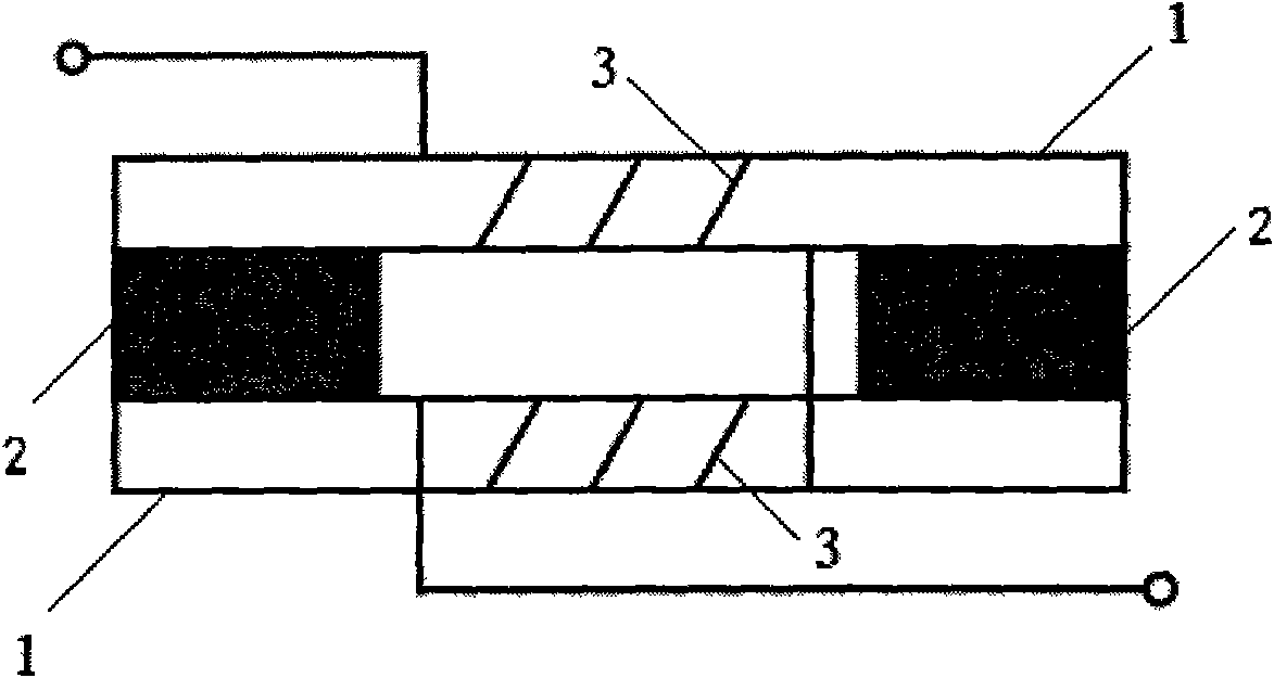
[0023] figure 1 It is the topological structure diagram of the permanent magnet bias type single-phase fault current limiter. Among them, the permanent magnet bias type three-phase fault current limiter can be equivalent to three permanent magnet bias type single-phase fault current limiters sharing one permanent magnet, that is, integrated. The two iron cores 1 are horizontal and linear, and the two copper wire windings 3 are respectively wound on the respective horizontal linear iron cores 1, and the two permanent magnets 2 are sandwiched between the two iron cores 1 respectively.
Embodiment 2
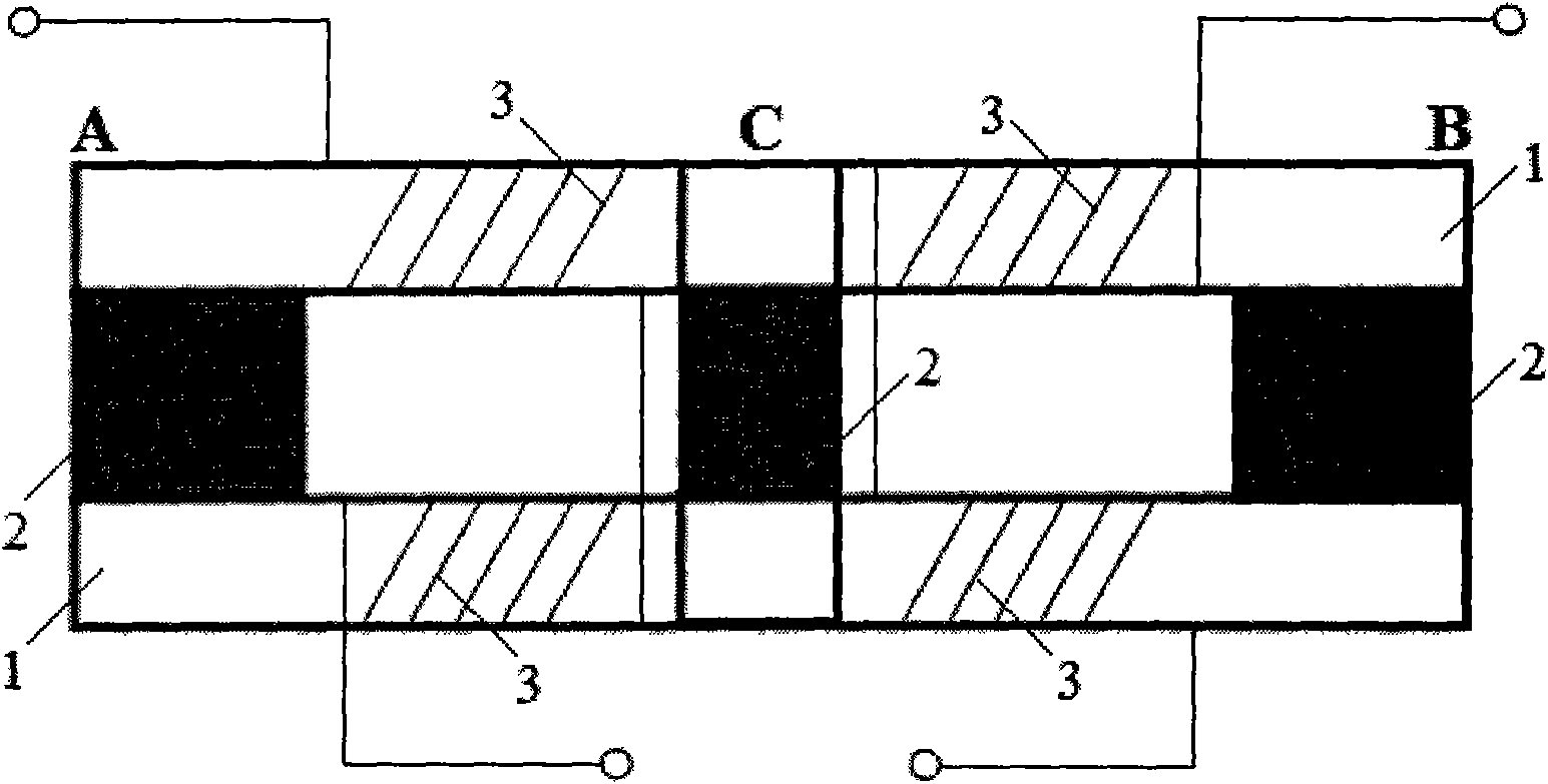
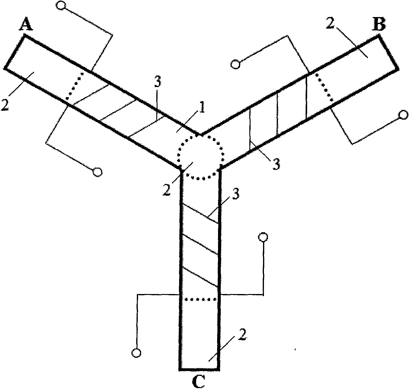
[0025] figure 2 , image 3 and Figure 4 A permanent magnet biased three-phase fault current limiter is presented, which includes:
[0026] The two iron cores 1 are in the shape of a three-pronged star placed horizontally, and are formed by cutting and stacking cold-rolled silicon steel sheets;
[0027] Six copper wire windings 3 are respectively wound on the bifurcated arms of the three-pronged star-shaped iron core placed horizontally. The corresponding ends of the copper wire windings on the two iron cores of each phase are connected and connected in series in A and B respectively. , C three-phase power supply network;
[0028] Four permanent magnets 2, wherein, three permanent magnets 2 are located at the ends of the bifurcated arms of the three-fork star core 1, and are sandwiched between the two iron cores 1, all of which are rectangular parallelepiped structures; another permanent magnet 2 It is located in the center of the trifurcated star-shaped iron core 1 and s...
PUM
 Abstract
Description
Claims
Application Information
 - R&D
- Intellectual Property
- Life Sciences
- Materials
- Tech Scout
- Unparalleled Data Quality
- Higher Quality Content
- 60% Fewer Hallucinations
Browse by: Latest US Patents, China's latest patents, Technical Efficacy Thesaurus, Application Domain, Technology Topic, Popular Technical Reports.
© 2025 PatSnap. All rights reserved.Legal|Privacy policy|Modern Slavery Act Transparency Statement|Sitemap|About US| Contact US: help@patsnap.com


