Spiral-flow type activated sludge biochemical treatment device with inner cylinder body

A biochemical treatment device, activated sludge technology, applied in water/sludge/sewage treatment, sustainable biological treatment, biological water/sewage treatment, etc. High-pressure air, limiting the depth of aerobic biochemical pools, etc., to achieve the effect of improving biochemical effects, maintaining sludge volume, and omitting sludge return

Inactive Publication Date: 2009-11-25
HAISIBOTE BEIJING SCIENE & TECH
View PDF0 Cites 1 Cited by
  • Summary
  • Abstract
  • Description
  • Claims
  • Application Information

AI Technical Summary

Problems solved by technology

[0002] Activated sludge aerobic biochemical reaction has been an important technology for organic sewage treatment for a long time. Its cost, treatment effect is good, and the equipment is simple. An important factor of the effect, the current aeration equipment mostly adopts the aeration head of various structures, the aeration head is set at the bottom of the sewage treatment equipment, and the high-pressure air supply pipe is connected to shoot out the air flow through the aeration head, so as to realize the air flow. Mixed mass transfer with sewage to achieve the effect of aeration. Due to the pressure limitation of the air source, this kind of aeration equipment can only be used within 5 meters of water depth. Too deep water will not be able to aerate, which also limits The depth of the aerobic biochemical pool increases the floor area of ​​the aerobic treatment system. In addition, the gas-liquid mass transfer effect of this method of launching air jets into the sewage is limited, which requires a lot of energy and high-pressure air

Method used


Image

  • Spiral-flow type activated sludge biochemical treatment device with inner cylinder body
  • Spiral-flow type activated sludge biochemical treatment device with inner cylinder body

Examples


Embodiment Construction

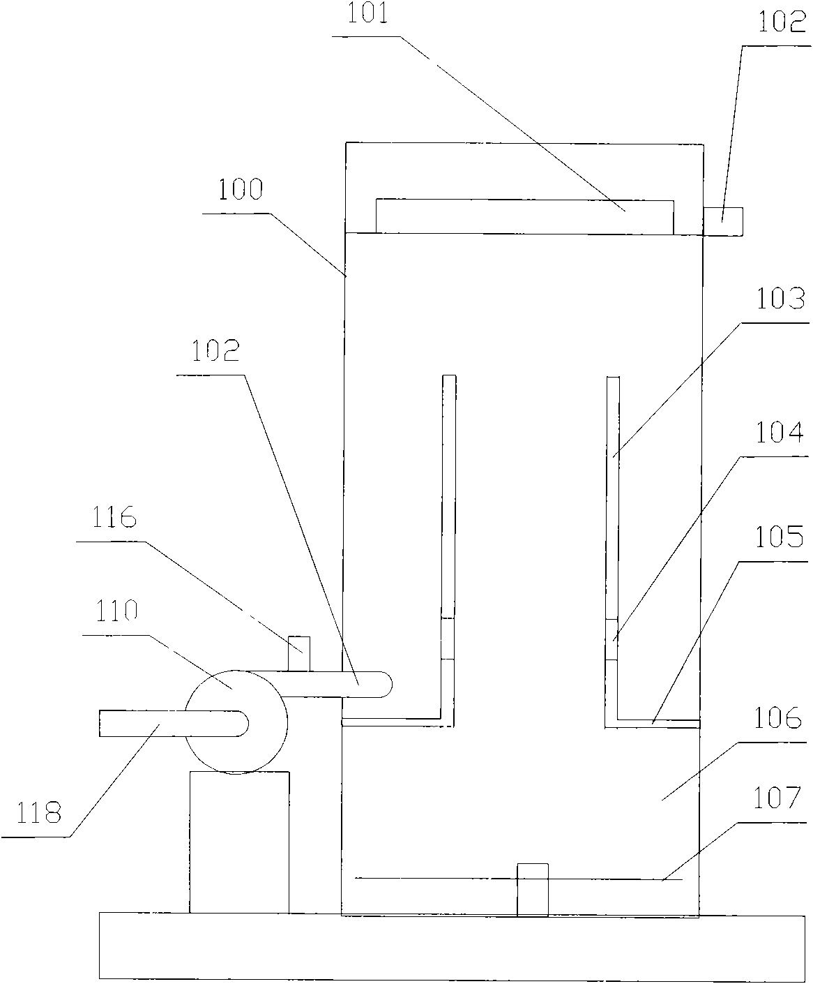
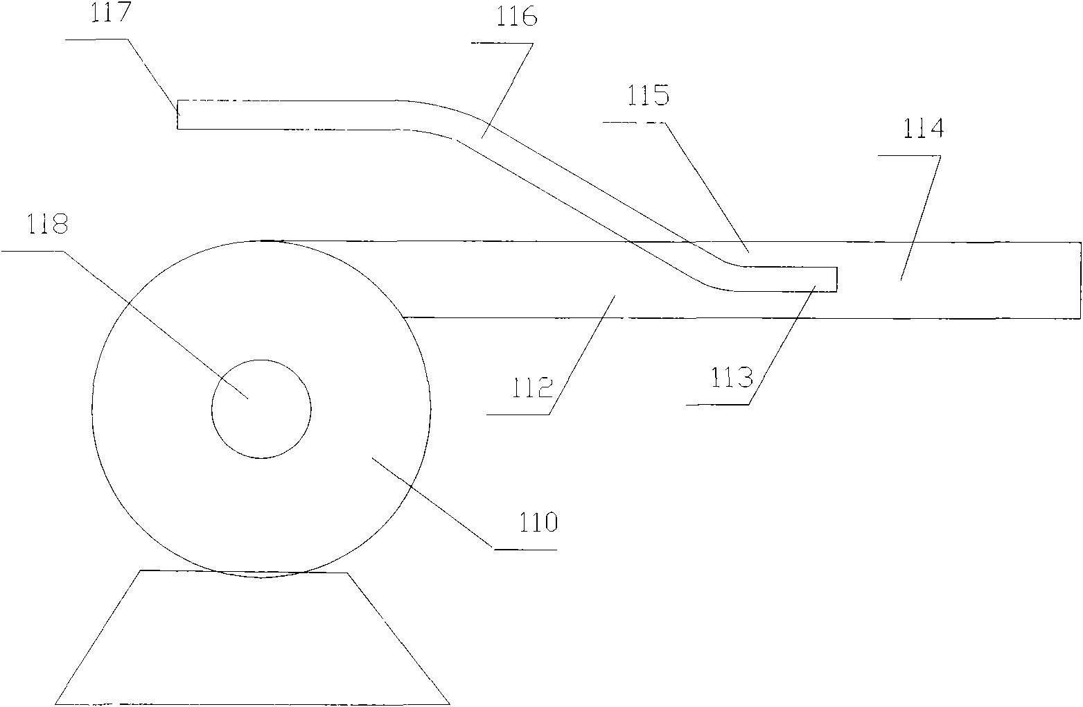
[0010] see figure 1 and 2 , the present invention relates to a swirl-type activated sludge biochemical treatment device with an inner cylinder, comprising a cylindrical shell 100 and a high-efficiency aeration device, the shell is provided with a Inner cylinder 103, the outer side of the lower end of the inner cylinder is connected to the inner wall of the housing through an annular partition 105, closing the space between the housing and the inner cylinder, and the lower part of the inner cylinder is provided with one or more layers The through-holes 104 are arranged circularly along the cylinder, and the jet aeration device includes a high-pressure water pump 110, a jet tube 112 and several air tubes 116, and the jet tube is installed on the outlet of the high-pressure water pump to form a high-pressure water pump The output pipe of the air pipe, the front end of the air pipe is located in the jet pipe, and the front opening of the air pipe is located inside the front openi...


PUM


Abstract

The invention relates to a spiral-flow type activated sludge biochemical treatment device with an inner cylinder body, which comprises a cylinder shell and a high-efficiency aeration device, wherein the inside of the shell is provided with the inner cylinder body opened widely at upper and lower ends; the outside of the lower end of the inner cylinder body is connected with the inner wall of the shell through a ring baffle; the lower part of the inner cylinder body is provided with a layer or a plurality of layers of through holes annularly distributed along the cylinder body; the high-efficiency aeration device comprises a high pressure water pump, a jet pipe, and a plurality of air pipes; the jet pipe is arranged on the outlet of the high pressure water pump and forms an output pipeline of the high pressure water pump; the front ends of the air pipes are positioned in the jet pipe; the front-end openings of the air pipes are positioned inside the front-end opening of the jet pipe; and the jet pipe is connected with the cylinder shell along the tangential direction of the cylinder shell and is communicated with the inner space of the cylinder shell, and the connection part is positioned above the baffle. The device allows deeper water depth, has low energy consumption and high activated sludge concentration, is beneficial for improving biochemical effect, and improves effluent water quality.

Description

technical field [0001] The invention relates to a sewage treatment device, in particular to a swirl-type activated sludge biochemical treatment device provided with an inner cylinder, and belongs to the technical field of environmental protection. Background technique [0002] Activated sludge aerobic biochemical reaction has been an important technology for organic sewage treatment for a long time. Its cost, treatment effect is good, and the equipment is simple. An important factor of the effect, the current aeration equipment mostly adopts aeration heads of various structures, the aeration head is set at the bottom of the sewage treatment equipment, connected to the high-pressure air supply pipe, and the air flow is shot out through the aeration head, so as to realize the air flow. Mixed mass transfer with sewage to achieve the effect of aeration. Due to the pressure limitation of the air source, this kind of aeration equipment can only be used within 5 meters of water dep...

Claims


Application Information

Patent Timeline
Patent Type & Authority Applications(China)
IPC IPC(8): C02F3/12
CPCY02W10/10
Inventor 陈光亮
Owner HAISIBOTE BEIJING SCIENE & TECH
Why Eureka
Try Eureka