Method for manufacturing rigid carbon fiber heat insulating material and surface treatment method

A technology of thermal insulation and manufacturing method, which is applied in the field of rigid carbon fiber thermal insulation materials and manufacturing, can solve the problems of low strength, increased thermal conductivity, short service life, etc., and achieves simple process, high stability and convenient operation. Effect

Active Publication Date: 2009-12-02
辽宁奥亿达新材料股份有限公司
View PDF0 Cites 39 Cited by
  • Summary
  • Abstract
  • Description
  • Claims
  • Application Information

AI Technical Summary

Problems solved by technology

The disadvantages of the soft carbon felt impregnation molding process are that the product strength is low, the product is easy to be layered and cracked under high temperature conditions, and the service life is short. Due to the relatively low strength, it is not convenient to disassemble and install; Felt, although the strength has been improved, the thermal conductivity of the product is increased, the thermal insulation performance is deteriorated, and the thermal insulation effect is reduced.

Method used


Image

  • Method for manufacturing rigid carbon fiber heat insulating material and surface treatment method
  • Method for manufacturing rigid carbon fiber heat insulating material and surface treatment method
  • Method for manufacturing rigid carbon fiber heat insulating material and surface treatment method

Examples


example 1

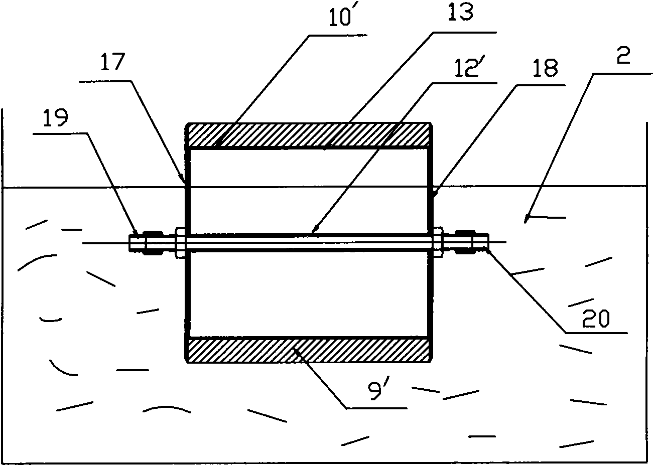
[0054] Isotropic pitch-based carbon fiber P-800 is used, the value represents the fiber length in microns, and P represents the ground product. Grind the mixture of carbon fiber and sucrose solution with concentrations of 30% and 50%, respectively, and add 0.8% carboxymethylcellulose dispersant. After the aspirator is formed to meet the thickness requirements, lift the aspirator out of the water and continue to suck for 30-150s. Specific steps are as follows:

[0055] (1) Isotropic pitch-based fibers were pulverized or ground to obtain short fibers with an average length of 800 μm.

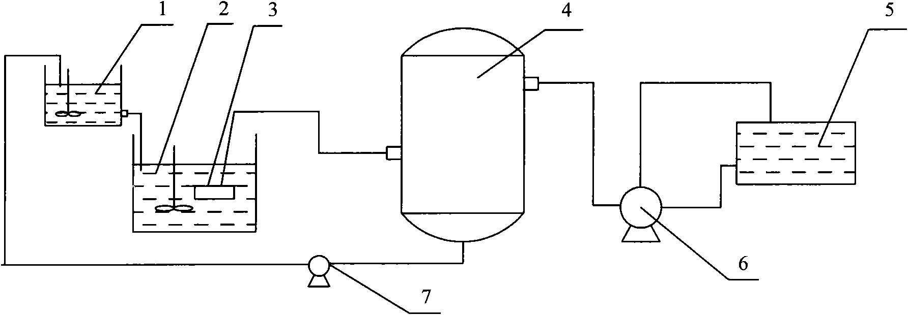
[0056] (2) if figure 1 As shown, the binder and carbon fiber are mixed in the mixing tank 1, and the weight percentages of the binder solution are 30% and 50% respectively.

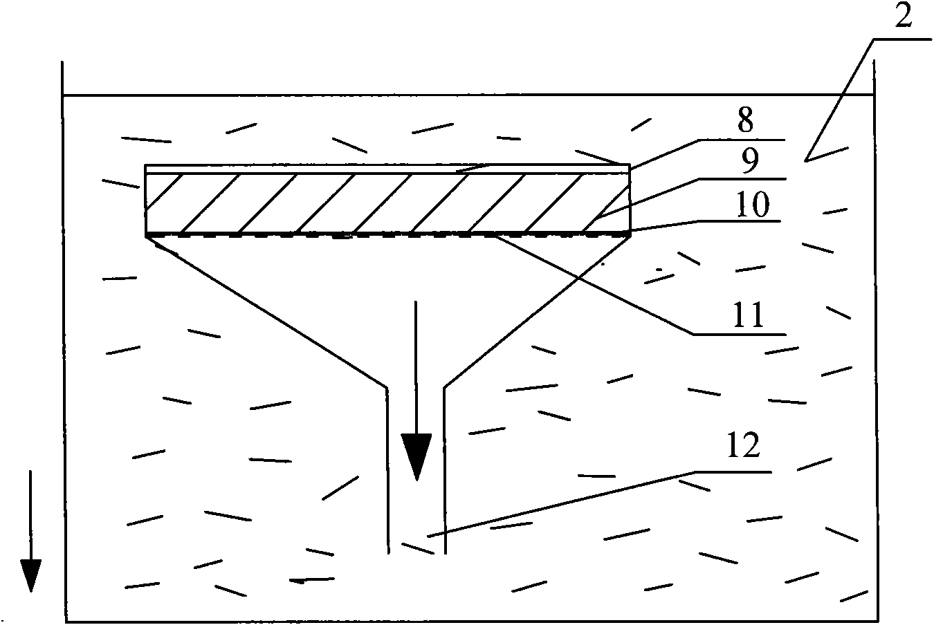
[0057] (3) if figure 1 , 2 As shown, the mixture of binder and carbon fiber is put into the molding tank 2 with the aspirator 3, and the aspirator 3 is used for suction molding for about 1 to 10 minutes. Adhesive and ca...

example 2

[0064] (1) Isotropic pitch-based carbon fiber P-800 is used, the value represents the fiber length in microns, and P represents the ground product. The mixture of carbon fiber and 30% sucrose solution is formed by the aspirator. After reaching the thickness requirement, lift the aspirator out of the water and continue to suck for 30-50s. The specific molding and carbonization steps are the same as Example 1, and the filming steps are as follows:

[0065] Carry out surface polishing treatment to the carbonized rigid heat insulating material 15 to make the surface smooth.

[0066] (2) The weight ratio of each component of the binder is phenolic resin: boron carbide = 100:100, and the high temperature binder can be obtained by mixing the phenolic resin and boron carbide evenly according to the above ratio.

[0067] (3) if Figure 4 As shown, a layer of high-temperature adhesive layer 16 is coated on the upper surface of the rigid thermal insulation material 15, and then graphit...


PUM

PropertyMeasurementUnit
lengthaaaaaaaaaa
densityaaaaaaaaaa

Abstract

The invention relates to method for manufacturing a rigid carbon fiber heat insulating material and a surface treatment method. In the method, mashed carbon fiber and caking agent are fully mixed with dispersant solution and molded by vacuum filtration and compression; infusibilization and carbonization treatment are carried out on the preformed product to obtain a rigid heat insulating material with high strength, low heat conductivity and low density. Surface treatment is carried out on the rigid heat insulating material for improving the surface properties, including surface polishing, graphite paper and carbon cloth paste, surface coating high-temperature hardening treatment, and the like. The rigid heat insulating material prepared by the method has the advantages of good performance of heat insulation, low heat capacity, low density, high strength, and the like.

Description

technical field [0001] The invention relates to the technical field of carbon fiber thermal insulation materials, which are used in rigid carbon fiber thermal insulation materials used in high temperature states such as crystal growth furnaces, crystal pulling devices, ceramic sintering furnaces, vacuum high-temperature heat treatment furnaces, and inert gas protection furnaces, and their manufacture. method. Background technique [0002] With the advancement of science and technology, there is a great demand for rare metals (such as molybdenum and tungsten) and magnetic materials in the fields of military, national defense and scientific research. The production of these materials is directly or indirectly related to high temperature furnaces and vacuum furnaces. In addition, in the field of industrial technology, the high-temperature treatment of workpieces or raw materials is completed in high-temperature vacuum furnaces or inert gas shielded furnaces. The temperature i...

Claims


Application Information

Patent Timeline
Patent Type & Authority Applications(China)
IPC IPC(8): C04B35/66C04B35/83
Inventor 郑淑云张作桢陈惠龙龙晓飞原天强刘成华王红伟崔欣
Owner 辽宁奥亿达新材料股份有限公司
Why Eureka
Try Eureka