Motor rotor positioning system for hybrid vehicle and positioning method thereof

A technology for hybrid electric vehicles and motor rotors, which is applied in the field of automobile manufacturing to achieve improved performance, simple positioning methods, and the elimination of measurement errors

Active Publication Date: 2009-12-02
CHERY AUTOMOBILE CO LTD
View PDF0 Cites 3 Cited by
  • Summary
  • Abstract
  • Description
  • Claims
  • Application Information

AI Technical Summary

Problems solved by technology

As a special operating environment, the production line of hybrid electric vehicles has strict time and space requirements for the workstations. The positioning of the motor rotor involves many factors such as assembly sequence, assembly space, and production efficiency. At present, there is no one suitable for automobiles. Automatic motor rotor positioning system and positioning method for production line characteristics

Method used


Image

  • Motor rotor positioning system for hybrid vehicle and positioning method thereof
  • Motor rotor positioning system for hybrid vehicle and positioning method thereof
  • Motor rotor positioning system for hybrid vehicle and positioning method thereof

Examples


Embodiment 1

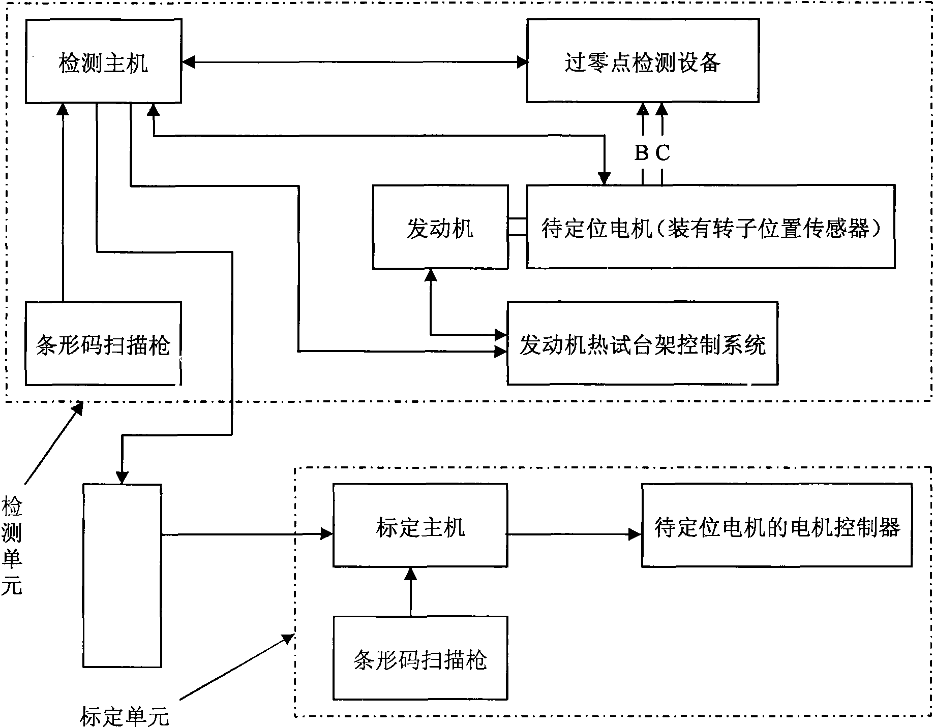
[0028] like figure 1 As shown, the hybrid vehicle motor rotor positioning system of this embodiment is composed of a detection unit and a calibration unit. , a barcode scanning gun for scanning motor barcodes, zero-crossing detection equipment and a motor rotor position sensor installed on the motor to be positioned, the detection host and engine hot test bench control system, barcode scanning gun, zero-crossing detection equipment and motor rotor The position sensor is connected; the calibration unit includes a barcode scanning gun and a calibration host, and the calibration host is connected to the motor controller of the motor to be positioned; the detection host and the calibration host are respectively connected to the storeable motor barcode number and rotor position angle through the network The database server connection for the value.

[0029] The detection host is a single-chip microcomputer with a network interface and its peripheral circuits.

[0030] The zero-cr...

Embodiment 2

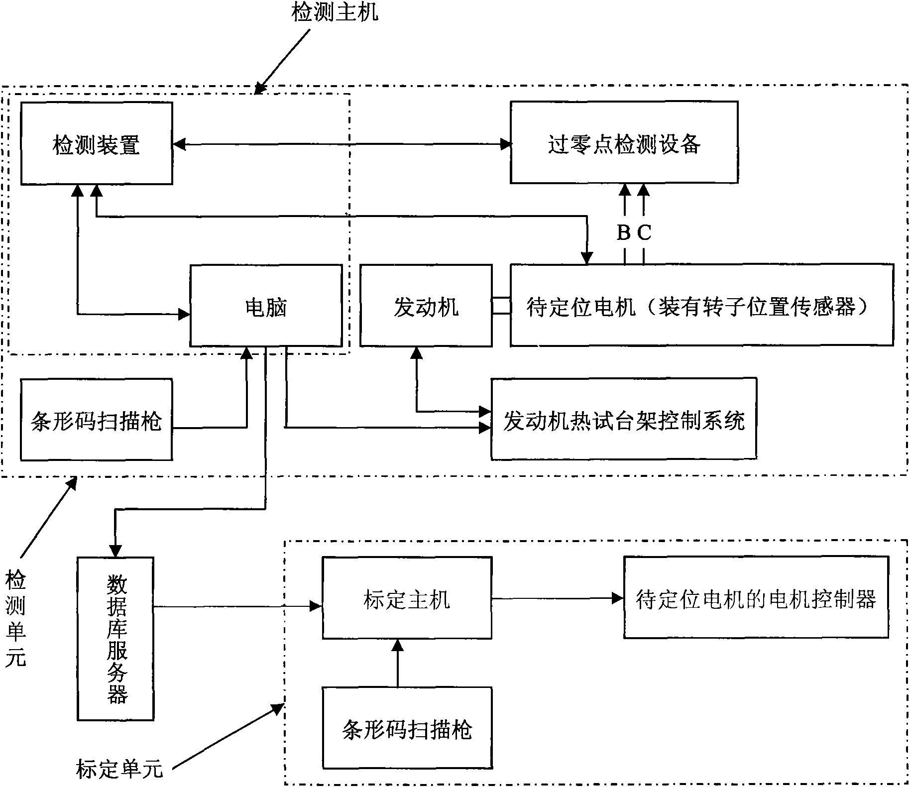
[0041] like image 3 As shown, the difference between this embodiment and Embodiment 1 is that the detection host of this embodiment is a combination of a detection device and a computer. The detection device is composed of a single-chip microcomputer and its peripheral circuits. , so that the existing resources can be fully utilized, the single-chip circuit and development difficulty can be simplified, and the anti-interference performance of the CAN network is strong, which is suitable for the complex electromagnetic environment of the production line.


PUM


Abstract

The invention aims to provide a motor rotor positioning system for a hybrid vehicle and a positioning method thereof, which are suitable for the characteristics of a vehicle production line. The positioning system consists of a detection unit and a calibration unit, wherein the detection unit comprises a power device capable of driving a motor to be positioned to rotate, a detection host computer, a bar code scanner, a zero crossing detection device and a motor rotor position sensor arranged on the motor to be positioned, and the detection host computer is connected with the power device, the bar code scanner, the zero crossing detection device and the motor rotor position sensor; the calibration unit comprises a bar code scanner and a calibration host computer, and the calibration host computer is connected with a motor controller of the motor to be positioned; and the detection host computer and the calibration host computer are connected with a database server through a network respectively. The detection host computer detects the position angle value of the motor rotor through the zero crossing detection device and the motor rotor position sensor, transmits the position angle value to the calibration host computer, and further writes the position angle value into the motor controller so as to finish the positioning of the motor rotor.

Description

technical field [0001] The invention belongs to the technical field of automobile manufacturing, and in particular relates to the installation of a motor of a hybrid electric vehicle. Background technique [0002] In recent years, with the continuous advancement of automobile and electronic technology, breakthroughs have been made in hybrid vehicles powered by internal combustion engines and electric motors. The electric motor, as the auxiliary power source of hybrid electric vehicles, is related to the power and stability of the whole vehicle Sex, plays a pivotal role. Permanent magnet synchronous motors with embedded permanent magnets have the advantages of efficient and adjustable speed operation, and are more and more widely used in hybrid vehicles. Precise control of the motor can not only improve the efficiency of the motor, but also improve the system efficiency of the vehicle , and to control the motor, it is necessary to precisely position the rotor of the motor. ...

Claims


Application Information

Patent Timeline
IPC IPC(8): H02P6/16
Inventor 宋波
Owner CHERY AUTOMOBILE CO LTD
Why Eureka
Try Eureka