New method and device for arbitrary beam shaping

A new method and beam technology, applied in optics, optical components, instruments, etc., can solve problems such as difficulties in the application of strong laser systems, low light energy utilization efficiency, and small uniformly irradiated areas, and achieve the effect of simplifying the composition of the system

Active Publication Date: 2009-12-30
NAT UNIV OF DEFENSE TECH
View PDF0 Cites 26 Cited by
  • Summary
  • Abstract
  • Description
  • Claims
  • Application Information

AI Technical Summary

Problems solved by technology

Among them, the binary optical element has the characteristics of high diffraction efficiency and adjustable spot profile, and can realize functions such as miniaturization, array, integration, and arbitrary wavefront transformation that are difficult to achieve with traditional optics. Its quality level is restricted by the development level of micro-fine processing technology. At present, the laser damage threshold of binary optical components is low, and there are still difficulties in the application of strong laser systems
The optical wedge array focusing optical system has simple processing technology, and there are no difficulties in materials and equipment to make devices with large aperture and high light loss resistance threshold, but the area to achieve uniform irradiation is small, and interference patterns are prone to appear
The use of amplitude-type liquid crystal spatial light modulators is a real-time, adjustable beam space shaping method, which can easily obtain the desired shape of near-field beams, but the laser damage threshold is low, which is only suitable for the front stage of high-power laser systems. And the energy utilization efficiency of the system is relatively low
The use of birefringent lens groups is flexible and convenient, and its transmittance function can be flexibly changed as the beam parameters change, unlike other methods that are only designed for specific beam parameters, but the processing and production of birefringent lens groups is difficult, and light energy can be used relatively low efficiency
Generally speaking, several laser beam shaping methods commonly used at present have their own defects.

Method used


Image

  • New method and device for arbitrary beam shaping
  • New method and device for arbitrary beam shaping
  • New method and device for arbitrary beam shaping

Examples


Embodiment Construction

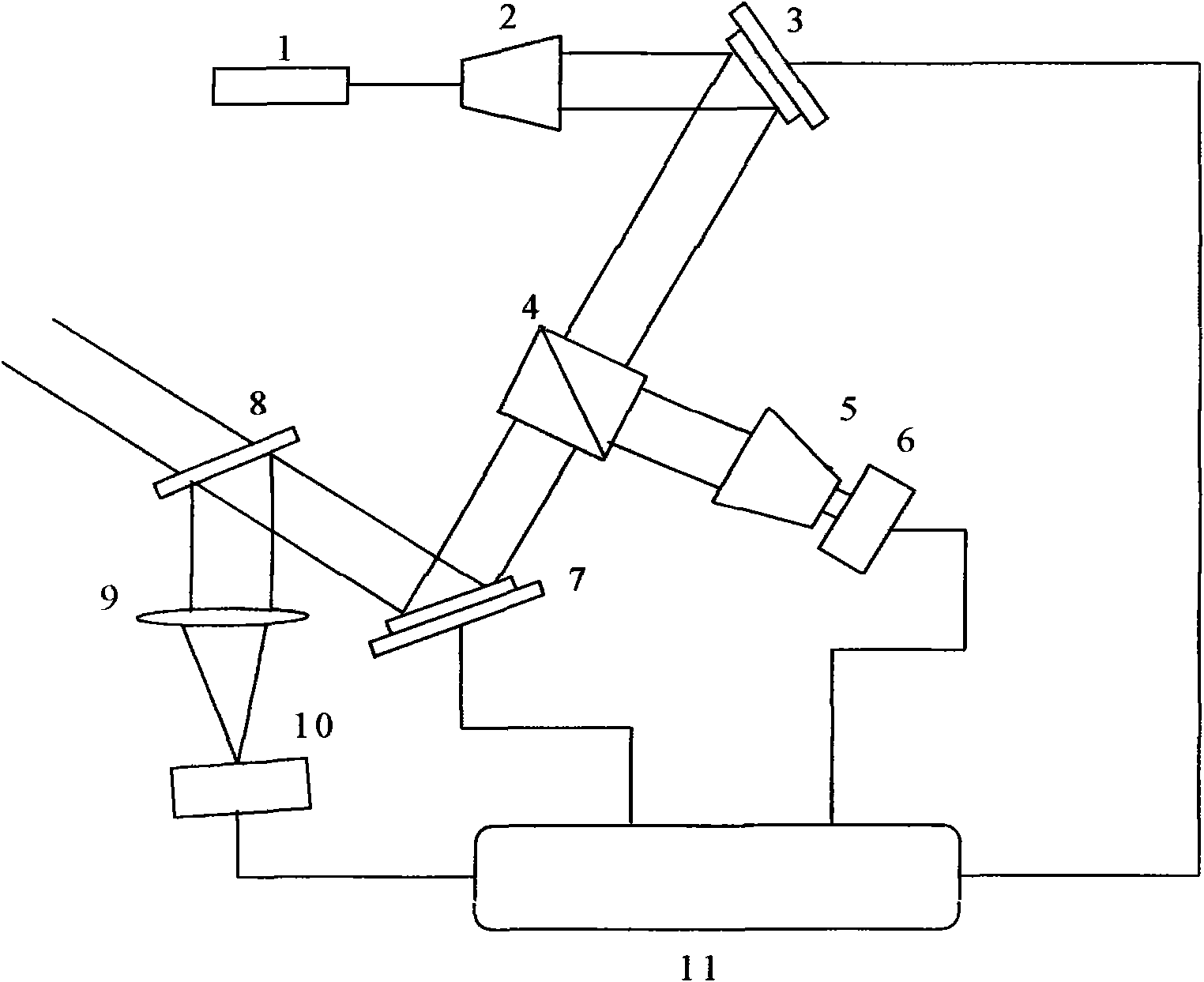
[0043] Such as figure 1 As shown, the whole system consists of a laser to be shaped 1, a beam expander 2, a first deformable mirror 3, a beam splitter 4, a beam shrinker 5, an image sensor 6, a second deformable mirror 7, a beam splitter 8, a focusing A lens 9, an image sensor 10, and an algorithm controller 11 are composed. The laser 1 is located before the beam expander 2, the first deformable mirror 3 is located behind the beam expander 2, the beam splitter 4 is located between the first deformable mirror 3 and the second deformable mirror 7, and the beam reducer 5 is located Between the beam mirror 4 and the image sensor 6, the focusing lens 9 is located between the beam splitter mirror 8 and the image sensor 10, the algorithm controller 11 communicates with the image sensor 6, the image sensor 10, the first deformable mirror 3, and the second deformable mirror 7 connections.

[0044] 1. First build the figure 1 In the platform shown, the laser light emitted by the lase...


PUM


Abstract

The invention relates to a new method and device for arbitrary beam shaping. The method can be used for shaping the light intensity of incident beam into required distribution and can effectively compensate beam wavefront phase change caused by light intensity shaping and an optical system self. The invention adopts a double shaping mirror and a double image senor combining an SPGD algorithm realizing device to form an adaptive closed loop shaping system, the image sensor is in charge of detecting far field and near field light intensity distribution information of shaped beam in real time, and an algorithm controller is in charge of feedback control on the shaping mirror, so as to correct light intensity distribution and phase distribution of the incident beam. The invention has the advantages of high efficiency and convenient use.

Description

technical field [0001] The invention relates to a new method and device for arbitrary shaping of beams, in particular to a new method and device for realizing arbitrary shaping of laser beams by using a random parallel gradient descent algorithm, which can correct the waves of the shaped beams while realizing arbitrary shaping of the beam intensity. Front phase distribution. Background technique [0002] In the field of laser technology, there are usually strict requirements on the distribution of laser beam energy. For example, in the fields of laser material processing and processing, inertial confinement fusion (ICF) and other fields, the energy distribution of the laser beam is usually required to be uniform, that is, the flat-top beam; and the hollow beam with no energy distribution in the center is used as a laser catheter, optical tweezers and optical wrench. At present, it has become a powerful tool to realize the precise manipulation and control of microscopic part...

Claims


Application Information

Patent Timeline
Patent Type & Authority Applications(China)
IPC IPC(8): G02B27/00G02B27/09G02B26/06
Inventor 马浩统周朴许晓军刘泽金陈金宝王小林马阎星李霄习锋杰汪晓波郭少锋吴武明姜宗福舒柏宏
Owner NAT UNIV OF DEFENSE TECH
Why Eureka
Try Eureka