Manufacturing method of wire rod with abrasive particle

A manufacturing method and technology of wire rods, applied in the field of wire rod manufacturing, can solve the problems of low material removal rate, low recovery rate, cost consumption, etc., and achieve the effect of high production efficiency and high adhesion

Inactive Publication Date: 2010-01-06
捷斯奥企业有限公司
View PDF0 Cites 6 Cited by
  • Summary
  • Abstract
  • Description
  • Claims
  • Application Information

AI Technical Summary

Problems solved by technology

[0002] With the development of high-tech industries, hard and brittle materials are widely used, especially ceramic materials are the most popular. Ceramic materials have high hardness and high temperature resistance, so they are often used in aerospace technology, semiconductors, optoelectronics, and information electronics industries, such as sapphire. Panels, silicon wafers, quartz masks, etc., but the ceramic materials have relatively high hardness and high brittleness, and processing is not easy, and because of the different uses of the various industries, it is necessary to use various precision processing instruments to process The ceramic material is processed, and the prior art cuts the ceramic material by using a wire saw to cut wafers
[0003] see Figure 1A and Figure 1B As shown, it is a schematic diagram of the prior art mechanism and processing. The cutting mechanism 1 of the technology is to wind the metal wire 12 on a plurality of rollers 11 in an equidistant manner, and soak the cutting mechanism 1 in a In the solution 13 of abrasive particles, when the roller 11 rotates, it also drives the metal wire 12 to advance, cutting the material 2 like a wire saw. At the same time, when the metal wire 12 cuts the material 2 , using the metal wire 12 to drive the free abrasive particles, so that the material 2 and the metal wire 12 are cut through the free abrasive particles, but the free abrasive particles have a small contact area with the material, resulting in material The removal rate is small, so a longer processing time is required. In addition, when it is necessary to process harder and more difficult-to-cut materials, the way of free abrasive particles will be difficult to achieve the expected cutting efficiency on the surface of the material 2, and it is necessary to A large amount of free abrasive particle solution 13 is processed, the recovery rate is low, it is not environmentally friendly and costly
[0004] Therefore, in order to improve the shortcomings of the prior art, a metal wire 15 with diamond abrasive grains on the surface has been developed. Please refer to figure 2 It is a cross-sectional view of the structure of a metal wire with diamond abrasive grains in the prior art. As the name implies, the metal wire with diamond abrasive grains 17 on the surface is to attach tiny diamond abrasive grains 17 to the surface of the metal wire 15. Electroplating or brazing is carried out, and the diamond abrasive grains 17 are attached to the metal wire 15 by solder 18. Compared with the prior art of processing by immersion, the metal with diamond abrasive grains 17 The wire 15 can be cut by electric discharge, but it cannot cut non-conductive materials, and can also be wound on a plurality of rollers for continuous cutting to save man-hours. In addition, the wire with diamonds has less cutting loss, so It is suitable for cutting materials such as semiconductors; the above-mentioned attachment of diamond or material particles with equivalent hardness to metal wires can achieve better cutting efficiency, but when manufacturing wires with abrasive grains on the surface, the abrasive grains on the surface cannot be firmly fixed On the wire rod, the efficiency of cutting will be reduced; so the prior art has the following disadvantages:
[0005] 1. Low removal rate;
[0006] 2. Consuming costs;
[0007] 3. It is not environmentally friendly to produce a large amount of waste liquid

Method used


Image

  • Manufacturing method of wire rod with abrasive particle
  • Manufacturing method of wire rod with abrasive particle
  • Manufacturing method of wire rod with abrasive particle

Examples


Embodiment Construction

[0030] The above and other technical features and advantages of the present invention will be described in more detail below in conjunction with the accompanying drawings.

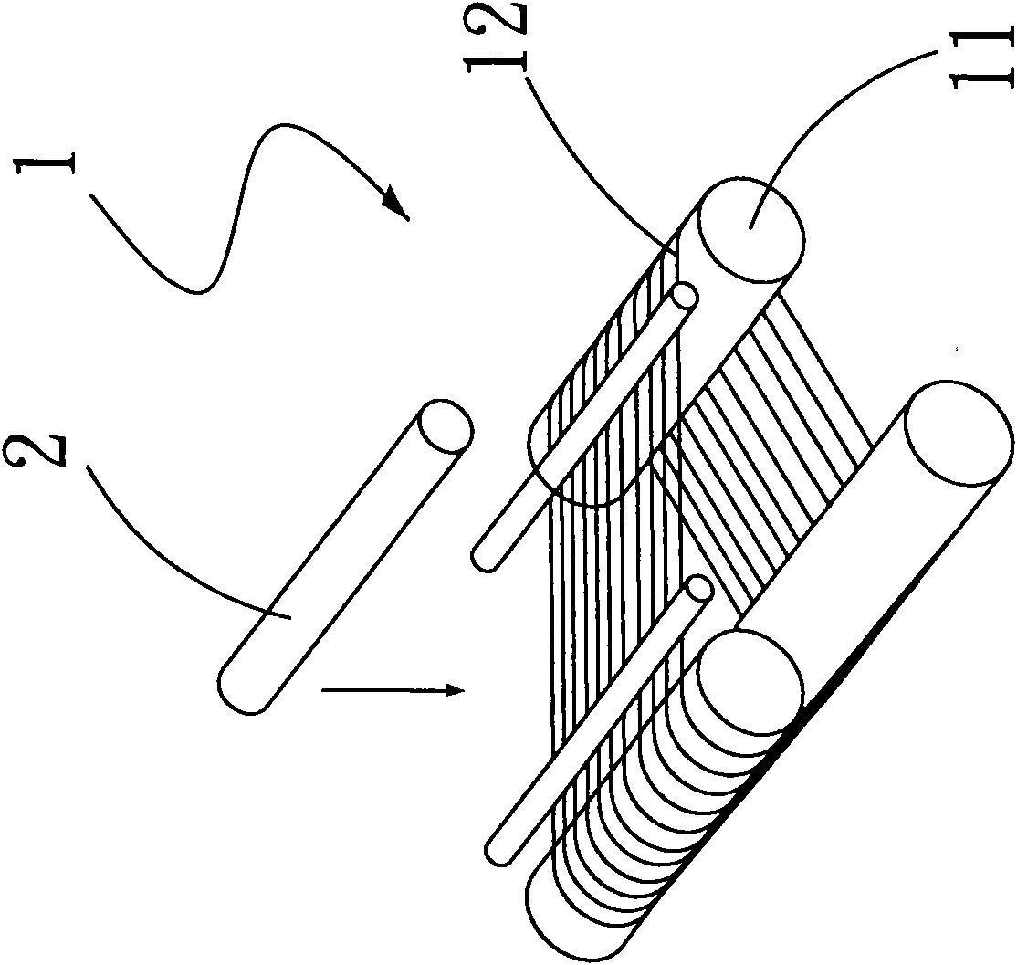
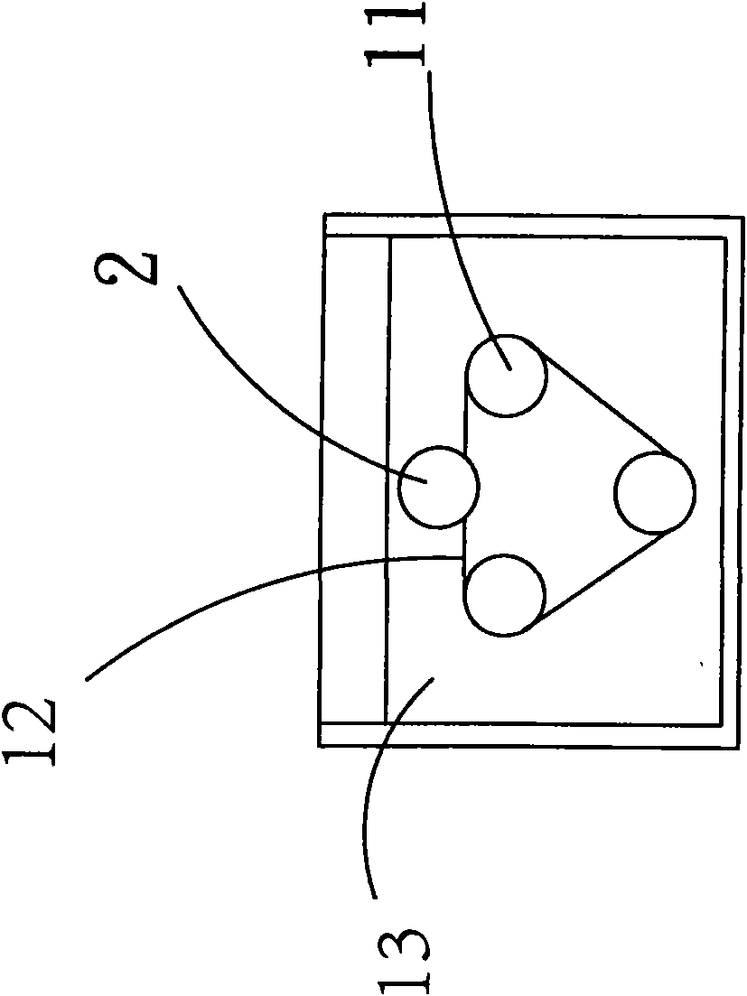
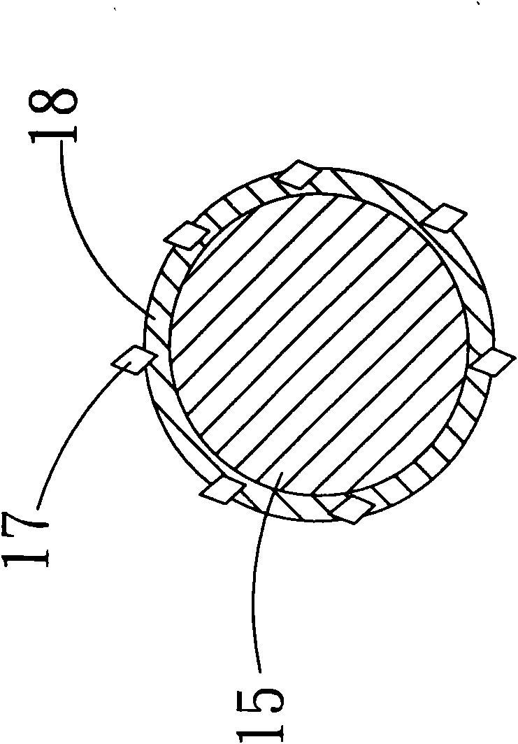
[0031] see image 3 , Figure 5 and Figure 6 , as shown in the figure, the manufacturing method of the embodiment of the present invention includes the following steps:

[0032] 31: Provide a wire 5 and at least one adhesive film 4, the surface of the adhesive film 4 is evenly distributed with abrasive grains 41 in advance;

[0033] Prepare a bare wire 5 in advance, and an adhesive film 4 with abrasive grains 41 uniformly distributed on at least one side;

[0034] 32: Provide at least one pair of first guide wheels 61, and place the wire and the adhesive film between the first guide wheels 61, crimp and press the adhesive film 4 by the guide groove of the first guide wheels 61, At the same time, the adhesive film 4 is heated, and the adhesive film 4 is heated by the first guide wheel 61, and shrinks a...


PUM


Abstract

The invention discloses a manufacturing method of wire rod with abrasive particles. An adhesive film with at least one side surface being evenly distributed with abrasive particles in advance and a wire rod pass through at least a pair of first idler pulleys; the wire rod and the adhesive film are placed between the first idler pulleys, the guide channels of the first idler pulleys coil and press the adhesive film, and the adhesive film is heated; after the adhesive film is heated by the first idler pulley, the adhesive film is contracted and tightened outside the wire rod so as to ensure that the abrasive particles and the adhesive film cover the surface of the wire rod.

Description

technical field [0001] The invention relates to a method for manufacturing a wire, in particular to a method for manufacturing a wire with abrasive grains attached to its surface. Background technique [0002] With the development of high-tech industries, hard and brittle materials are widely used, especially ceramic materials are the most popular. Ceramic materials have high hardness and high temperature resistance, so they are often used in aerospace technology, semiconductors, optoelectronics, and information electronics industries, such as sapphire. Panels, silicon wafers, quartz masks, etc., but the ceramic materials have relatively high hardness and high brittleness, and processing is not easy, and because of the different uses of the various industries, it is necessary to use various precision processing instruments to process The ceramic material is processed. In the prior art, the ceramic material is cut by using a wire saw to cut wafers. [0003] see Figure 1A an...

Claims


Application Information

Patent Timeline
IPC IPC(8): B28D5/04B24D18/00
Inventor 李政民黄俊彦
Owner 捷斯奥企业有限公司
Why Eureka
Try Eureka