Resin-poured reel iron core transformer

A resin casting and winding iron core technology is applied in the field of winding iron core transformers, which can solve the problems of easy accumulation of dust and affect insulation performance, and achieve the effects of reducing noise, enhancing short-circuit impact resistance and reducing loss.

Active Publication Date: 2010-01-06
南京苏特电气股份有限公司
View PDF1 Cites 5 Cited by
  • Summary
  • Abstract
  • Description
  • Claims
  • Application Information

AI Technical Summary

Problems solved by technology

[0003] Patent document CN2703313Y discloses a "three-dimensional triangular coiled iron core dry-type transformer", which uses a coiled iron core, and its high and low voltage coils are wrapped with insulating layers. The core and the high and low voltage coils are vacuum pressure impregnated with insulating varnish. The transformer of this structure is a non-encapsulated dry-type wound core power transformer. Since the transformer coils of this structure are not encapsulated, it is easy to accumulate dust and affect Insulation performance, so it can only be used in closed environment
[0004] In the actual production process of existing cast coil core transformers, the iron core and wire package are generally produced separately and then assembled, that is, the open coil core is pre-processed, and the cast low-voltage and high-voltage coils are sequentially opened Load the coiled iron core, and then fold back the opening of the coiled iron core for butt joint. Since the iron core has opening loss, the loss level of the casting transformer using this open coiled iron core can only reach S11

Method used


Image

  • Resin-poured reel iron core transformer
  • Resin-poured reel iron core transformer
  • Resin-poured reel iron core transformer

Examples


Embodiment Construction

[0019] The accompanying drawings disclose the basic structure of the present invention without limitation, and the present invention will be further described below in conjunction with the embodiments.

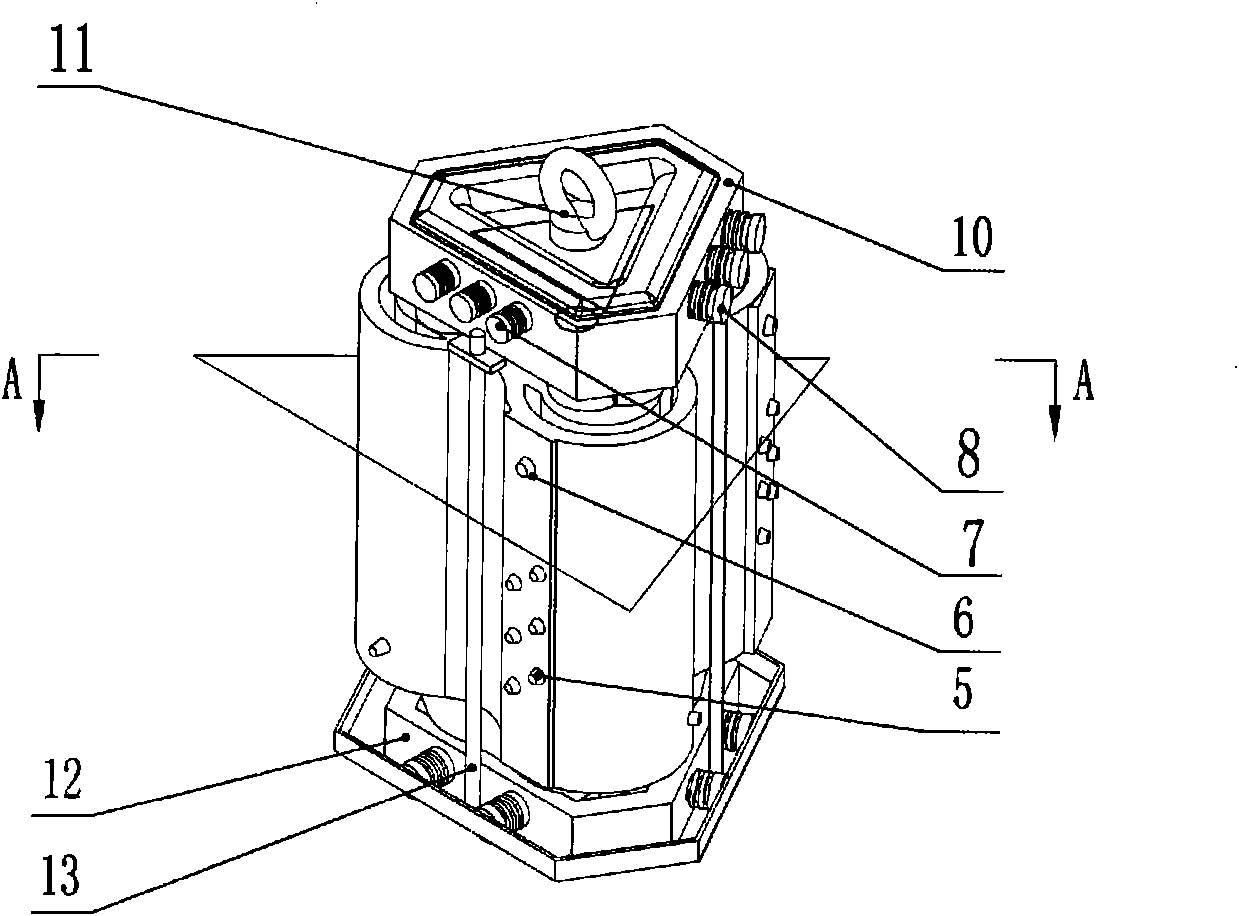
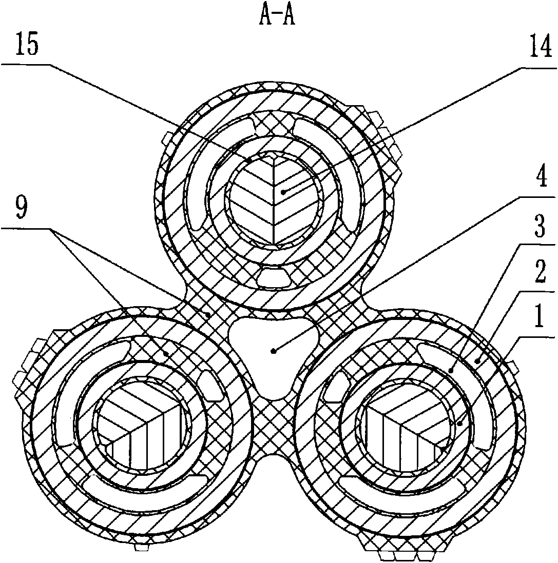
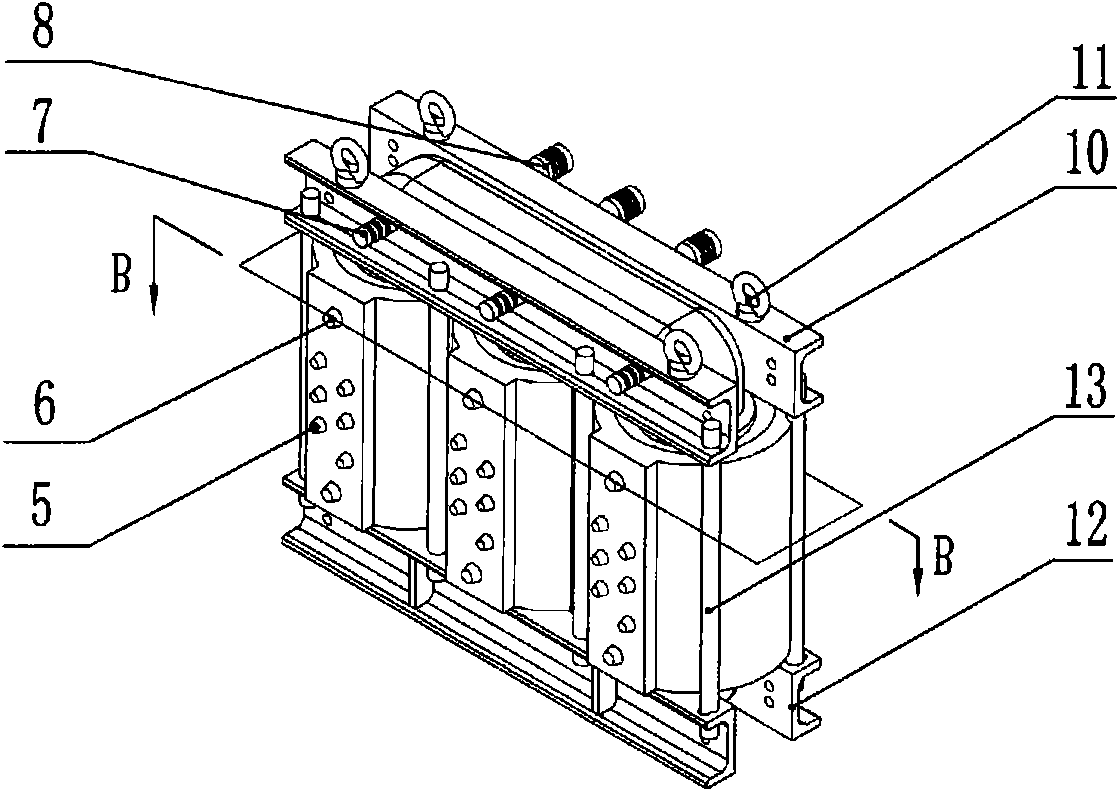
[0020] Depend on figure 1 with figure 2 It can be seen that the iron core in this embodiment is a three-dimensional triangular wound iron core 14 formed by combining three independent single-frame wound iron cores, and a coil bobbin 15 is arranged on the same iron core column of the three-dimensional triangular wound iron core, and the coil bobbin 15 The low-voltage wire package 1 and the high-voltage wire package 2 are wound on top, and the low-voltage wire package 1 and the high-voltage wire package 2 are casted by epoxy resin 9 to form a whole. There is also a central airway 4 in the center of the wire pack. The upper part of the triangular coiled iron core is provided with an upper end clamp 10, the lower part is provided with a lower end clamp 12, and the upper end cla...


PUM


Abstract

The invention relates to a resin-poured reel iron core transformer which is composed of an iron core, a high-voltage line package, a low-voltage line package, an upper end part clamp and a lower end part clamp, a high-voltage outgoing line insulator and a low-voltage outgoing line insulator. The iron core is a solid triangle or plane reel iron core, but no opening for installing the high-voltage line package and the low-voltage line package is arranged on the reel iron core. The high-voltage line package and the low-voltage line package on the same iron core column are solidified into one body by epoxy resin cure, or the high-voltage line package and the low-voltage line package on the same iron core column and the iron core are solidified into one body by epoxy resin cure, or the high-voltage line package and the low-voltage line package on each iron core column are solidified into one body by epoxy resin cure, or the high-voltage line package and the low-voltage line package on each iron core column and the iron core are solidified into one body by epoxy resin cure. The resin-poured reel iron core transformer has the advantages that as the reel iron core has no opening, the noload current and noise of the reel iron core are low; the high-voltage line package and the low-voltage line package are poured into one body by the epoxy resin cure, thereby enhancing the short circuit resisting and anti-shocking capacity of the transformer. As the high-voltage line package and the low-voltage line package are poured into one body, the processing difficulty and production cost are reduced.

Description

technical field [0001] The invention relates to a wound iron core transformer, in particular to a resin cast wound iron core transformer. Background technique [0002] Transformers are commonly used power equipment in power systems. The iron cores of power transformers are mainly in the form of laminated cores and coiled cores. Among them, the laminated cores have a large reluctance, resulting in large no-load current and high no-load loss. The iron core of the iron core has obvious advantages in these aspects; the types of power transformers mainly include oil-immersed power transformers and dry-type power transformers. Oil-immersed power transformers need insulating oil for insulation and heat dissipation, so maintenance and operation The cost is high; dry-type power transformers have obvious advantages in these aspects; dry-type wound core power transformers have integrated most of the advantages of existing transformer technologies, and have become the main development d...

Claims


Application Information

Patent Timeline
Patent Type & Authority Applications(China)
IPC IPC(8): H01F27/24H01F27/32H01F41/02
Inventor 薛建仁丁晓东薛韬
Owner 南京苏特电气股份有限公司
Why Eureka
Try Eureka