
Method for preparing continuous-fiber partially-reinforced aluminum alloy parts

A technology of aluminum alloy parts and local reinforcement, applied in the field of preparation of aluminum alloy precision castings, can solve the problems of high cost, difficult to control the arrangement and distribution, difficult to prepare prefabricated parts, etc.

Inactive Publication Date: 2010-01-20
JIANGSU UNIV
View PDF0 Cites 5 Cited by
  • Summary
  • Abstract
  • Description
  • Claims
  • Application Information

AI Technical Summary

Problems solved by technology

However, filamentous reinforcing fiber filaments are usually small in diameter and flexible, and it is difficult to control their arrangement and distribution, making the preparation of prefabricated shapes difficult and costly

Method used

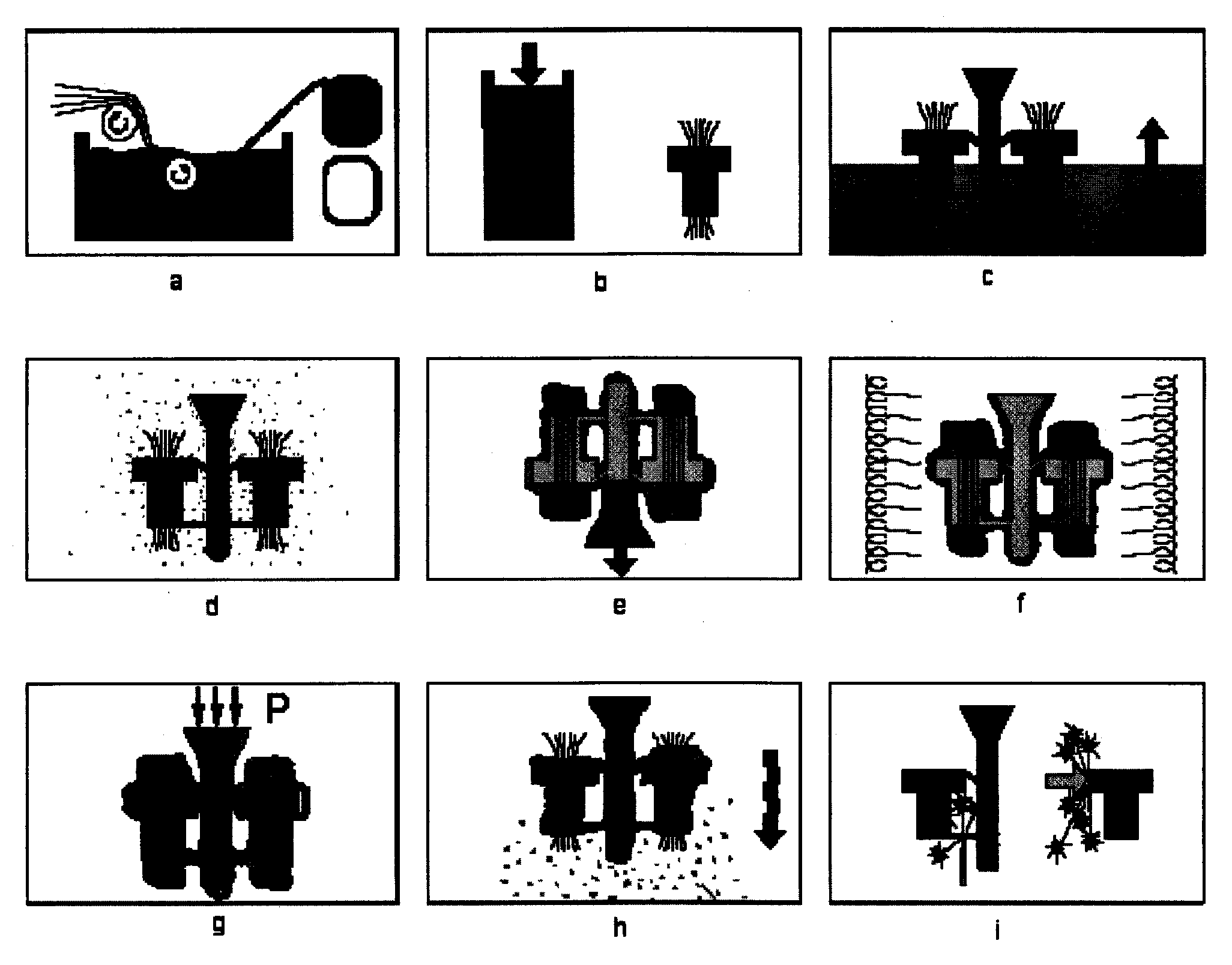

Image

  • Method for preparing continuous-fiber partially-reinforced aluminum alloy parts
  • Method for preparing continuous-fiber partially-reinforced aluminum alloy parts
  • Method for preparing continuous-fiber partially-reinforced aluminum alloy parts

Examples


Embodiment 1

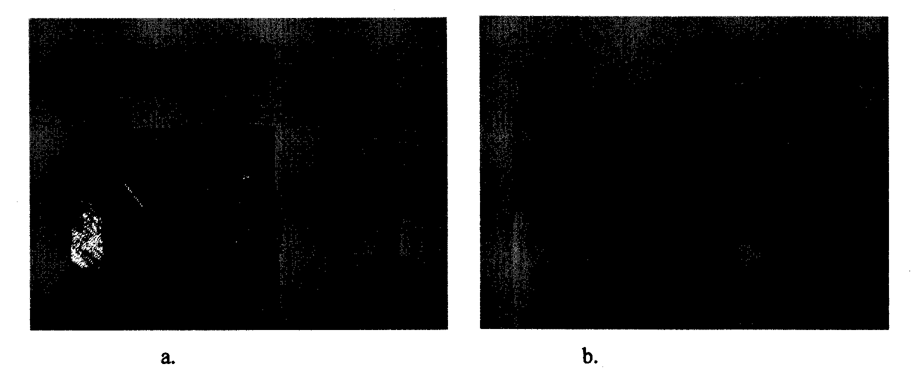
[0018] According to the process of the above invention, 50% volume fraction γ-Al is produced 2 O 3 Fiber (produced by Sumitomo Chemical Company, Japan, model Altex SN, fiber diameter 15μm, tensile strength 1.8GPa) reinforced aluminum alloy (Al-6%Zn-1%Mg-0.1%Cu) test bar, test block and continuous fiber Partially reinforced aluminum alloy test block. figure 2 a is the blank photos of these three samples, figure 2 b is the processed sample. The test bars and small test blocks are integrally reinforced by continuous fibers for performance testing. The large test block is locally reinforced by continuous fibers, the middle of the test block is a reinforced area, and both sides are non-reinforced areas. The use of the test block can verify the process feasibility of the present invention and measure the macroscopic internal stress in the reinforced area and the non-reinforced area. The measured tensile strength and elastic modulus of the 50% fiber reinforced aluminum alloy composi...

Embodiment 2

[0020] The fiber locally reinforced aluminum alloy sports bicycle crank connecting rod produced by the invention replaces the original high-strength forged steel parts, and the weight can be reduced by about 69%. The middle part of the connecting rod adopts 45% volume percentage γ-Al 2 O 3 The fiber (produced by Sumitomo Chemical Company, Japan, model Altex SN, fiber diameter 15μm, tensile strength 1.8GPa) is locally reinforced, and the matrix material is cast aluminum silicon alloy. The ceramic slurry adopts zircon powder refractory material and silica sol binder, the surface layer (two layers) is made of zircon powder (particle size 0.25mm), and the reinforcement layer is mollite powder (particle size 0.8-1.4mm) , The mold shell has 8 layers and the thickness is about 20mm. Dewaxing is carried out in a steam kettle with a pressure of 0.6 MPa and a pressure holding time of 90 seconds. The mold shell is fired in an electric furnace, and the firing temperature is 850°C. Since ...


PUM

PropertyMeasurementUnit
Diameteraaaaaaaaaa
Tensile strengthaaaaaaaaaa

Abstract

The invention relates to a preparation technology of precise alloy castings, in particular to a method for preparing continuous-fiber partially-reinforced aluminum alloy parts. The method comprises the following steps: putting fiber bundles in a high-temperature wax pool; arranging the fiber bundles in a corresponding part of a part wax pattern when a wax layer is fully cooled to the room temperature; then, directly manufacturing the part wax pattern with reinforced fibers on a wax injector; welding and combining with a casting system to be an integral wax pattern system; forming a ceramic pattern shell outside the wax pattern system by a plurality of times of dipping and sand-suspension cycles; fully drying the ceramic pattern shell for dewaxing and roasting; casting a liquid aluminum alloy on the ceramic pattern shell; immediately pressing a pattern shell molded cavity with argon after casting is finished; and fully solidifying and cooling to obtain the continuous-fiber partially-reinforced aluminum alloy parts. The invention does not need to specially manufacture a prefabricated fiber model and favorably solves the problems of treating, aligning and arranging fiber yarn in a casting model.

Description

Technical field [0001] The invention relates to the preparation technology of aluminum alloy precision castings, in particular to a method for preparing continuous fiber locally reinforced aluminum alloy parts. This method combines the preparation of wax molds and reinforced fiber preforms in the traditional investment casting process, uses gas pressure to fill and solidify liquid metal under pressure, and uses the characteristics of investment precision casting to directly produce continuous (Long) fiber partially reinforced aluminum alloy parts. Background technique [0002] Continuous fiber locally reinforced aluminum alloy precision castings, using high-strength fibers to enhance the high tensile stress area during service, have the load-bearing capacity, fatigue resistance and service performance that ordinary aluminum alloy castings can’t match, and the specific strength and strength that steel parts can’t match. Lightweight advantage, as structural parts, it can be widely...

Claims


Application Information

Patent Timeline
IPC IPC(8): C22C47/08
Inventor 孙少纯赵玉涛
Owner JIANGSU UNIV
Learn More