Single-stage forward type high-frequency linked inverter

A high-frequency transformer and forward-type technology, which is applied in the field of power electronic converters, can solve the problems of not maximizing device utilization, limiting the maximum duty cycle of switching tubes, and high voltage stress of switching tubes, so as to improve the equivalent duty cycle. Duty ratio and inductor current pulsation frequency, increase equivalent switching frequency and equivalent duty ratio, and reduce the effect of voltage stress

Inactive Publication Date: 2010-01-27
NANJING UNIV OF AERONAUTICS & ASTRONAUTICS
View PDF2 Cites 12 Cited by
  • Summary
  • Abstract
  • Description
  • Claims
  • Application Information

AI Technical Summary

Problems solved by technology

[0004] Chinese patent CN1758521A proposes a set of single-stage bidirectional step-down DC converter-type high-frequency link inverters, and Chinese patent CN101414791A proposes a set of differential step-down DC chopper-type high-frequency link inverters. The basic idea of ​​the high-frequency link inverter is composed of two identical high-frequency electrical isolation bidirectional power flow DC converters that output anti-phase low-frequency sinusoidal pulsating DC voltage to form an inverter. The two DC converters output sine waves respectively. The positive half-cycle waveform and the negative half-cycle waveform, so in any half cycle of the output sine wave, there is always a DC converter in an idle state, so the utilization of the device is not maximized
In the above two patents, the high-frequency link inverter composed of the forward converter is also mentioned. Due to the special problem of the magnetic reset of the forward converter transformer, the maximum duty cycle of the switching tube is limited, and the switching tube’s higher voltage stress

Method used


Image

  • Single-stage forward type high-frequency linked inverter
  • Single-stage forward type high-frequency linked inverter
  • Single-stage forward type high-frequency linked inverter

Examples


Embodiment Construction

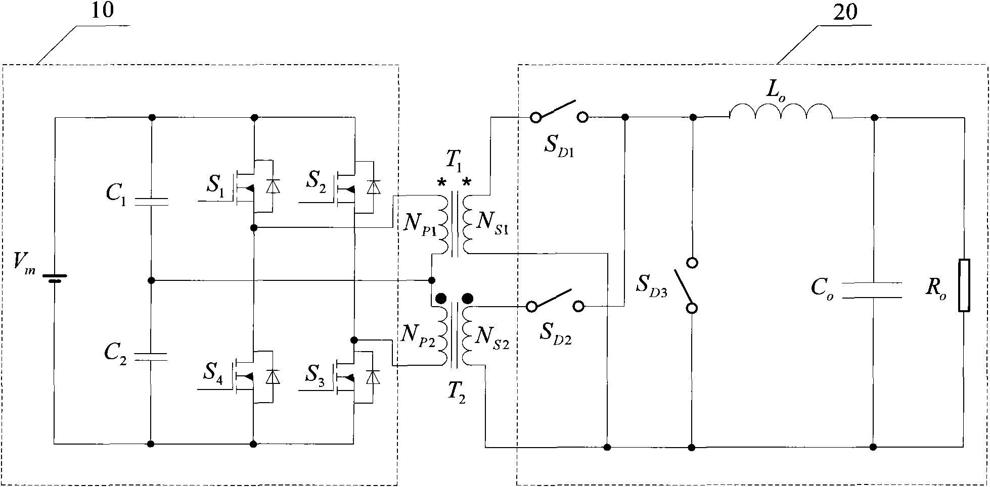
[0021] like figure 1 As shown, the structure of the single-stage forward high-frequency link inverter of the present invention includes: a primary side circuit 10, a first high-frequency transformer T 1 , the second high frequency transformer T 2 and the secondary side circuit 20, wherein: the primary side circuit 10 includes a DC power supply V in , the first voltage dividing capacitor C 1 , the second voltage dividing capacitor C 2 , the first power switch tube S 1 , the second power switch tube S 2 , the third power switch tube S 3 and the fourth power switch S 4 , DC supply V in The positive poles of are respectively connected to the first voltage dividing capacitor C 1 One end of the first power switch tube S 1 The drain and the second power switch S 2 the drain of the DC supply V in The negative poles of are respectively connected to the second voltage dividing capacitor C 2 One end of the fourth power switch tube S 4 The source and the third power switch S ...


PUM


Abstract

The invention discloses a single-stage forward type high-frequency linked inverter belonging to the field of power electronic inverter and comprising a primary side circuit, a first high-frequency transformer, a second high-frequency transformer and a secondary side circuit, wherein the primary side circuit comprises a power supply, two voltage-dividing capacitors and four power switch pipes; the first high-frequency transformer and the second high-frequency transformer both comprise primary side windings and secondary side windings; and the secondary side circuit comprises three four-quadrant high-frequency power switch, a filter inductor, a filter capacitor and a load. The single-stage forward type high-frequency linked inverter is formed in such a way that two two-way power flow forward converter units are in series connected at input ends in a staggered way and in parallel connected at output ends in the staggered way, the two two-way power flow forward converter units work in the staggered way all the time, and diodes of switch pipe bodies realize the magnetic resetting of the high-frequency transformers. The invention has low voltage stress of primary and secondary side switch pipes, low capacity of the voltage-dividing capacitors and high transformation efficiency and reliability, is suitable for a medium voltage input occasion and a high voltage input occasion and especially has extensive application prospect in a new energy power generation field.

Description

technical field [0001] The invention relates to an inverter, in particular to a single-stage forward high-frequency link inverter, which belongs to the field of power electronic converters. Background technique [0002] The inverter is a power conversion device that uses power semiconductor devices to convert DC power into AC power for AC loads. The inverter with high-frequency electrical isolation between the output AC load and the input DC power supply is called a high-frequency link inverter. The high-frequency electrical isolation components mainly play the following roles in the inverter: (1) Realize the The electrical isolation between the inputs improves the safety, reliability and electromagnetic compatibility of the inverter operation; (2) The matching between the inverter output voltage and the input voltage is realized, that is, the input voltage is allowed to be in a wide range The quality of the output voltage is guaranteed when changing, and its application ra...

Claims


Application Information

Patent Timeline
Patent Type & Authority Applications(China)
IPC IPC(8): H02M7/537
Inventor 吴红飞张犁邢岩
Owner NANJING UNIV OF AERONAUTICS & ASTRONAUTICS
Why Eureka
Try Eureka