Liquid expander

A liquid expansion and casing technology, which is applied in the field of liquid expanders for low-temperature and high-pressure liquid throttling and pressure reduction, to achieve the effects of flexible braking, reduced energy consumption, and zero leakage

Active Publication Date: 2010-02-10
XI AN JIAOTONG UNIV +1
View PDF0 Cites 12 Cited by
  • Summary
  • Abstract
  • Description
  • Claims
  • Application Information

AI Technical Summary

Problems solved by technology

[0003] The purpose of the present invention is to provide a kind of all-liquid expander for liquid throttling, which can effectively solve the negative impact brought by the coke-soup throttling valve in the existing traditional air separation process

Method used


Image

  • Liquid expander
  • Liquid expander
  • Liquid expander

Examples


Embodiment Construction

[0015] The present invention will be described in further detail below in conjunction with the accompanying drawings and embodiments.

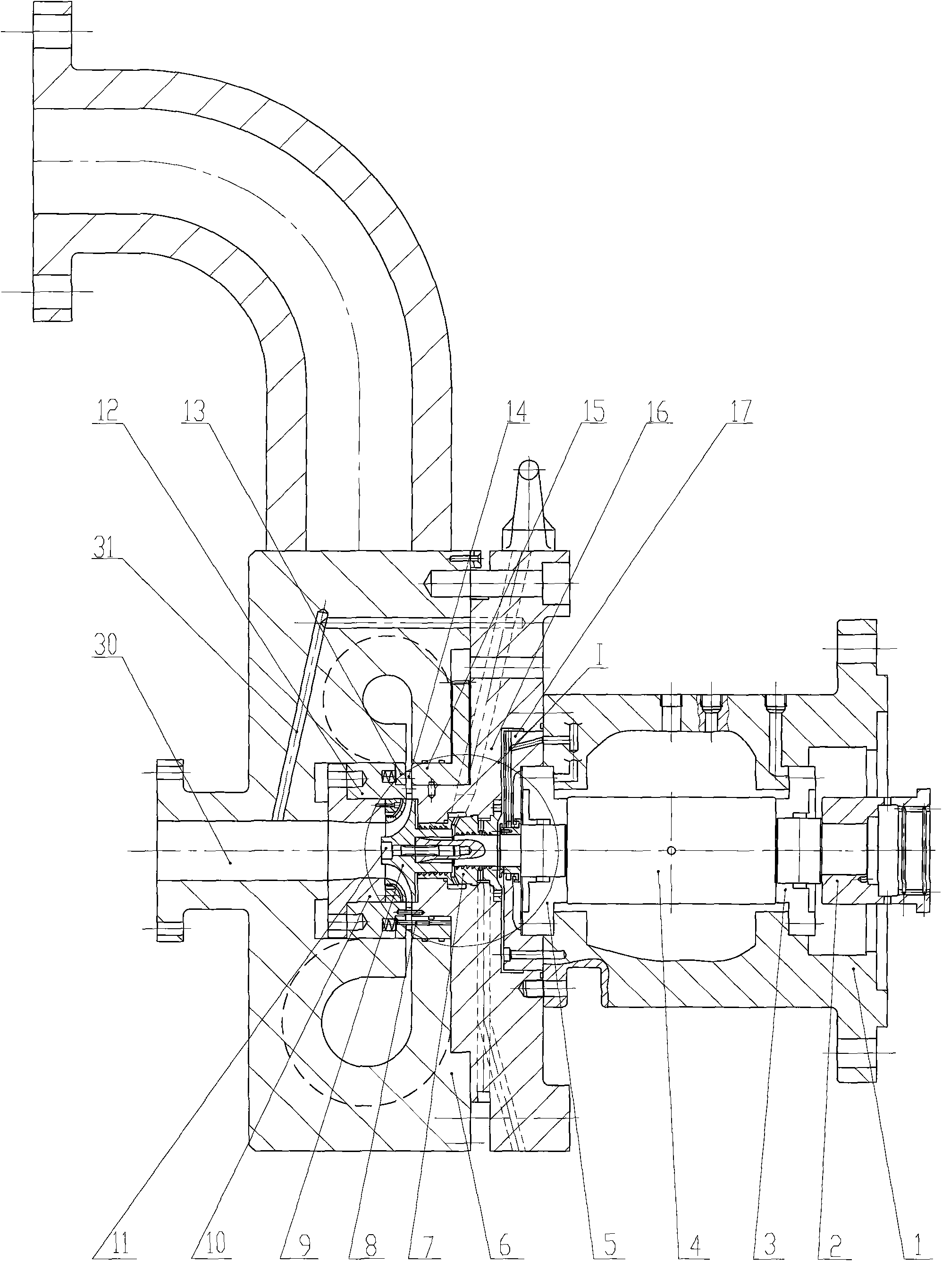
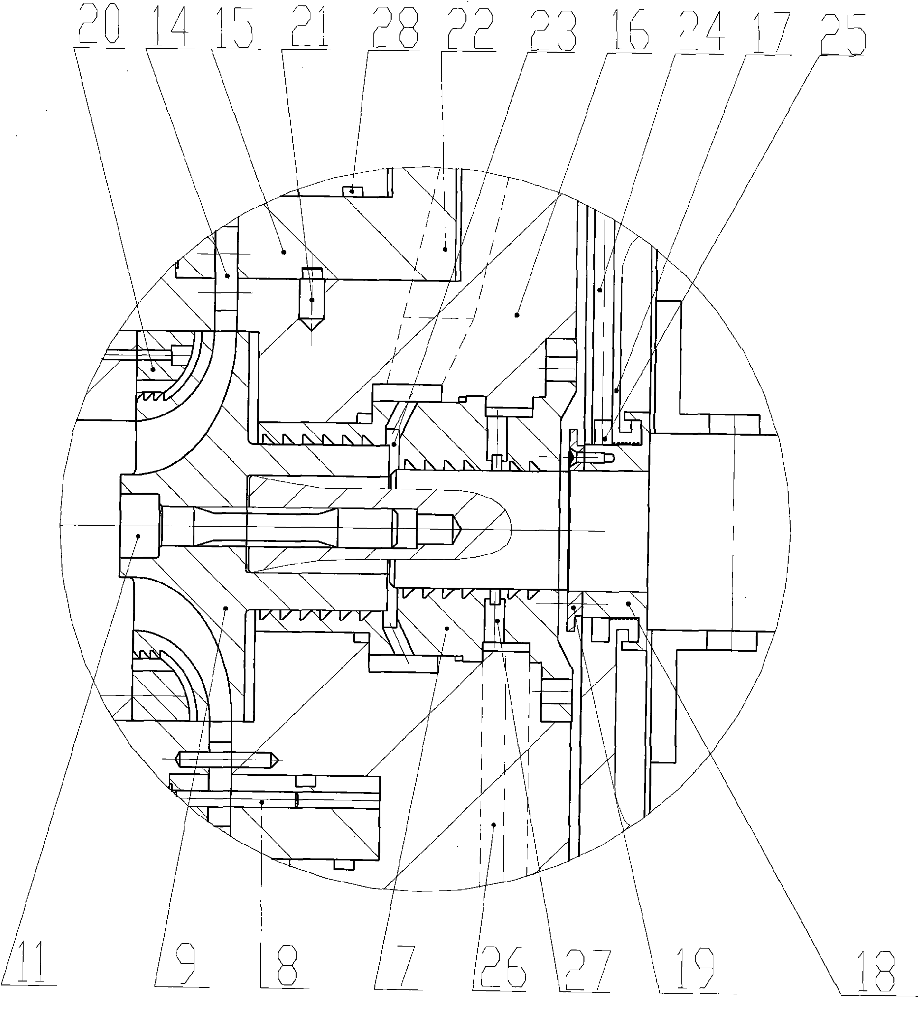
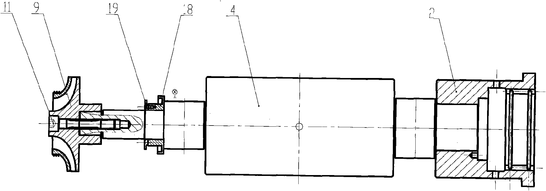
[0016] Such as figure 1 figure 2 As shown, an expander for liquid throttling includes a bearing housing 1; support-thrust bearings 3, 5, a rotor; an intermediate piece 17; a nozzle assembly; The casing 6 includes a working fluid inlet pipe and a working fluid outlet 30 , and a hole 31 and a designed volute guide channel are processed inside the casing 6 . The rotor includes a main shaft 4, an oil throwing ring 18 and an impeller 9 are arranged at the front of the main shaft 4, and the impeller 9 is connected with the main shaft through an impeller positioning screw 11, and a coupling 2 is arranged at the rear end. The nozzle assembly includes a nozzle platen 12 , a nozzle cover 13 , a nozzle vane 14 , a nozzle turntable 15 and a nozzle chassis 16 , and the nozzle cover 13 , nozzle vane 14 and nozzle turntable 15 are axially connected togeth...


PUM


Abstract

The invention discloses a liquid expander comprising a bearing box, a rotor, a spray nozzle assembly and an expander casing. The liquid expander is characterized in that the spray nozzle assembly comprises a spray nozzle press plate, a spray nozzle cover, a spray nozzle vane, a spray nozzle turntable and a spray nozzle chassis, wherein the spray nozzle cover, the spray nozzle vane and the spray nozzle turntable are sequentially connected together in an axial direction by a cylinder pin, and the spray nozzle press plate and the spray nozzle cover are elastically connected in the axial direction; the spray nozzle turntable is connected on the external diameter of a step circle of the spray nozzle chassis in a circumferential rotation way; both axial ends of the spray nozzle chassis are respectively connected with the expander casing and the bearing box; a middle component is arranged between the bearing box and the axial direction of the spray nozzle chassis; the rotor comprises a main shaft, the front part of the main shaft is provided with an oil thrower, and the back part of the main shaft is provided with a shaft coupling; shaft necks at both sides of the main shaft are fixed inthe bearing box in a rotation way, and the front end of the main shaft passes through the spray nozzle and the middle component and is connected with an impeller;]the oil thrower is positioned at theposition of the middle component in the axial direction; and a position from the wheel back side of the impeller to the main shaft section of the oil thrower is provided with a shaft sealer in the axial direction, and the shaft sealer has a compound sealed structure.

Description

technical field [0001] The invention relates to a liquid expander, in particular to a liquid expander for throttling and reducing pressure of low temperature and high pressure liquid. Background technique [0002] In air separation, nitrogen liquefaction, liquefied natural gas, hydrocarbon processing and other liquefaction circulation devices, the obtained high-pressure liquid needs to be depressurized according to the process requirements. At present, the traditional coke-soup liquid throttle valve is usually used to complete it, but it is a typical irreversible process, which will cause energy waste of high-pressure liquid, and dissipate it in the low-temperature system, resulting in temperature rise and loss of cooling capacity of the system. Moreover, the flow state of the pressure-reducing liquid using the throttle valve changes drastically, and vaporization easily occurs, which reduces the gas extraction rate of the air separation plant and increases the total energy c...

Claims


Application Information

Patent Timeline
Patent Type & Authority Applications(China)
IPC IPC(8): F01D1/02F01D9/02F01D5/02F01D11/00F01D25/18F01D25/24F01D25/16F01D5/14
Inventor 孙金菊王科宋鹏蔡国成付栋梁
Owner XI AN JIAOTONG UNIV
Why Eureka
Try Eureka