Beacon optical axis precision positioning system in atmosphere laser communication system

An atmospheric laser communication and precise positioning technology, which is applied in the transmission system, electromagnetic wave transmission system, optics, etc., can solve the problem that the technical index of tracking accuracy cannot be improved, the main optical axis of the laser beam cannot be accurately determined, and the positioning accuracy is impossible. It can achieve the effect of large volume, weight reduction and volume reduction

Inactive Publication Date: 2010-02-17
CHANGCHUN UNIV OF SCI & TECH
View PDF0 Cites 49 Cited by
  • Summary
  • Abstract
  • Description
  • Claims
  • Application Information

AI Technical Summary

Problems solved by technology

[0004] The laser beam is disturbed by atmospheric turbulence during the transmission of the atmospheric channel, the energy and polarization characteristics of the laser are affected, and the spot is distorted, which no longer conforms to the Gaussian distribution characteristics as a whole. Therefore, the traditional spot centroid algorithm of the detector can no longer To accurately determine the main optical axis of the laser beam, the positioning accuracy of the system cannot be made very high. Generally, the target tracking system accuracy of positioning sensors is greater than 15-20μrad. The schematic diagram of a typical device is as follows: figure 1 (Reference 1 Luo Tong, et al., Design and Realization of Beam APT of Free Space Optical Communication Ground Demonstration System, Applied Optics, Vol. 23, No. 2, 2002. The main components of the structure), and the optical axis of many other laser space communication systems The positioning device is also basically the same as document 1, namely figure 1 (The main references are: 2 Zeng Hualin, et al., Research on Space Optical Communication ATP System, Optical Technology, Volume 31, No. 1, January 2005; 3 Tan Jing, et al., Optical Wireless Communication Beam Alignment / Tracking Technology, "Laser Magazine", Vol. 26, No. 3, 2005; 4 Yue Bing, et al., Experimental System for Fast Tilting Mirror Precision Tracking in Space Optical Communication [J]. Optoelectronic Engineering, 2002, 29 (3): 35-42; 5 Xu Kehua, et al., Research on Beam Aiming Technology in Deep Space Optical Communication, Optical Precision Engineering, Volume 14, No. 1, February 2006; 6 Zhou Yalin, Ai Yong, Zuo Tao, Bao Libo. Real-time capture, tracking experiment and analysis of space beams, Acta Photonica Sinica, Vol. 34, No. 6, 2005; 7 Wang Pingping, Ai Yong, Zhi Xinjun. Design and Application of APT System in Free Space Optical Communication Terminals. Laser 2003, Vol. 1223, No. 6; 8 Su Xiuqin, Wang Fei, Liu Wen. A new method to improve the data processing speed of CCD target measurement. Acta Photonica Sinica, 2001, 30(7): 864~867Su X Q, Wang F, Liu W.Acta Photonica Sinica, 2001, 30( 7): 864~867; 9Hohn, D.H.Effects of atmospheric turbulence on the transmission of a laserbeam at 6328A.I-Distribution of intensity Applied Optics IP, vol.5, Issue 9, p.1427; 10 Foreign space laser communication technology development Situation. Internal data. October 2005.), all detectors are ordinary CCD detectors
For laser communication systems, such tracking accuracy cannot further improve the technical indicators of communication

Method used


Image

  • Beacon optical axis precision positioning system in atmosphere laser communication system
  • Beacon optical axis precision positioning system in atmosphere laser communication system
  • Beacon optical axis precision positioning system in atmosphere laser communication system

Examples


Embodiment Construction

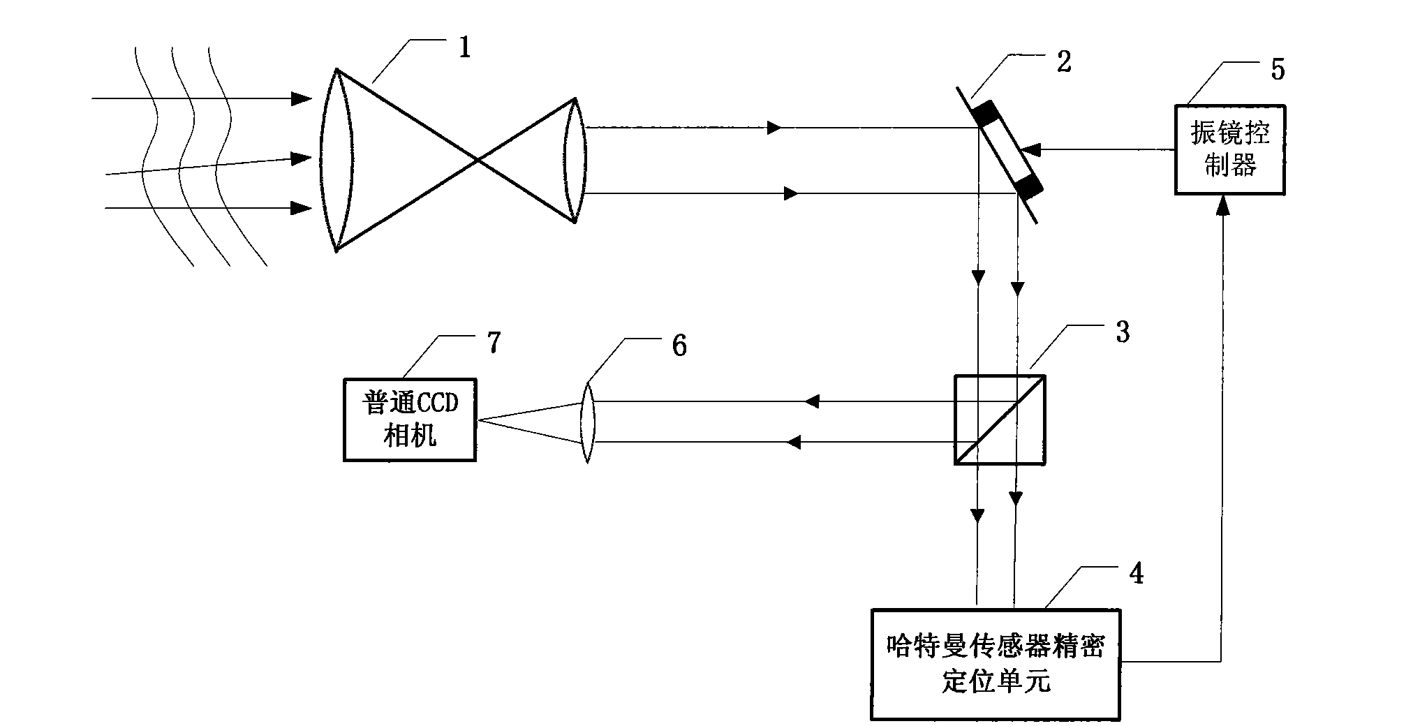
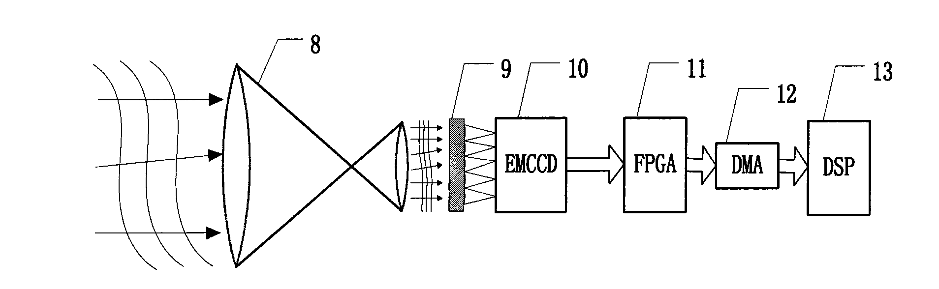
[0038] A beacon optical axis precision positioning system in an atmospheric laser communication system, characterized in that, such as figure 1 As shown, the system is composed of an optical receiving antenna (1), a vibrating mirror (2), a beam splitting prism (3), a Hartmann sensor optical axis precision positioning unit (4), a vibrating mirror controller (5), a lens (6 ) and an ordinary CCD camera (7); wherein the Hartmann sensor optical axis precision positioning unit (4) is composed of a beam reducer (8), a microlens array (9), an EMCCD high frame rate camera (10), and an FPGA on-site It consists of a programmable gate array (11), a DMA controller (12) and a DSP digital signal processing unit (13);

[0039] The optical receiving antenna (1) and the vibrating mirror (2) are coaxially arranged, and the mirror surface of the vibrating mirror (2) is placed at an angle of 45 degrees to the outgoing beam of the optical receiving antenna (1);

[0040] The dichroic prism (3) is p...


PUM


Abstract

The invention relates to a beacon optical axis precision positioning system in an atmosphere laser communication system, which is characterized by comprising an optical receiving antenna (1), a vibrating mirror (2), a dispersion prism (3), a Hartmann sensor optical axis precision positioning unit (4), a vibrating mirror controller (5), a lens (6) and a common CCD camera (7). To realize the real-time correction of the pointing direction of a beacon optical axis, the beacon optical axis precision positioning system detects a beacon light beam by a Schack Hartmann sensor with microlenses array and reconstructs a real-time wavefront image by a Zernike Polynomial mode method, thereby resolving the real pointing direction of the beacon optical axis of the atmosphere laser communication system and achieving final optical axis positioning precision exceeding 2 mu rad. If a common CCD positioned at a receiving end needs to obtain same resolution ratio and measuring precision, an optical systemof the common CCD has large volume and heavier weight; in addition, compared with the traditional platform, the invention has obviously reduced volume and weight, thereby effectively meeting the requirement of future space laser communication for the light type of an onboard platform.

Description

technical field [0001] The invention relates to a precise positioning system for a beacon optical axis in an atmospheric laser communication system, and belongs to the technical field of space laser communication. The system is mainly used for the precise positioning of the beacon optical axis in the atmospheric laser communication system. Background technique [0002] The core technology of atmospheric laser communication technology is acquisition, alignment and tracking APT (Acquisition Pointing Tracking) technology. Atmospheric laser communication has become a new direction for the development of optical communication due to its advantages of high bandwidth, high code rate, high confidentiality and anti-interference, and has become a research hotspot in various countries. The narrow laser emission beam has led to many technical challenges in beam alignment, and the research on APT technology is particularly important. Fast and accurate acquisition, aiming and tracking a...

Claims


Application Information

Patent Timeline
Patent Type & Authority Applications(China)
IPC IPC(8): H04B10/10G02B26/06G01B11/27H04B10/11
Inventor 景文博王晓曼姜会林刘智刘树昌段锦王彩霞付强祝勇
Owner CHANGCHUN UNIV OF SCI & TECH
Why Eureka
Try Eureka