
Oil and smoke purifier of low-temperature plasma synergistic modified filtering membrane

A low-temperature plasma and oil fume purifier technology, which is applied in the fields of filtration and separation, oil fume removal, chemical instruments and methods, etc., can solve the problems of concentration drop, the purification effect of high concentration oil fume needs to be further improved, etc., and achieves reduced pressure drop and simple structure. , to avoid the effect of electrode corrosion

Inactive Publication Date: 2010-02-24
陈明功
View PDF3 Cites 31 Cited by
  • Summary
  • Abstract
  • Description
  • Claims
  • Application Information

AI Technical Summary

Problems solved by technology

The plasma method uses a large number of active free radicals excited by its high energy to degrade the soot particles and reduce its concentration; in the process of plasma generation, the instantaneous high energy generated by high frequency discharge opens the chemical bonds of some harmful gases, making them Decompose into simple atoms or harmless molecules; but the purification effect of pure plasma method on high-concentration oil fume needs to be further improved

Method used


Image

  • Oil and smoke purifier of low-temperature plasma synergistic modified filtering membrane
  • Oil and smoke purifier of low-temperature plasma synergistic modified filtering membrane

Examples


Embodiment 1

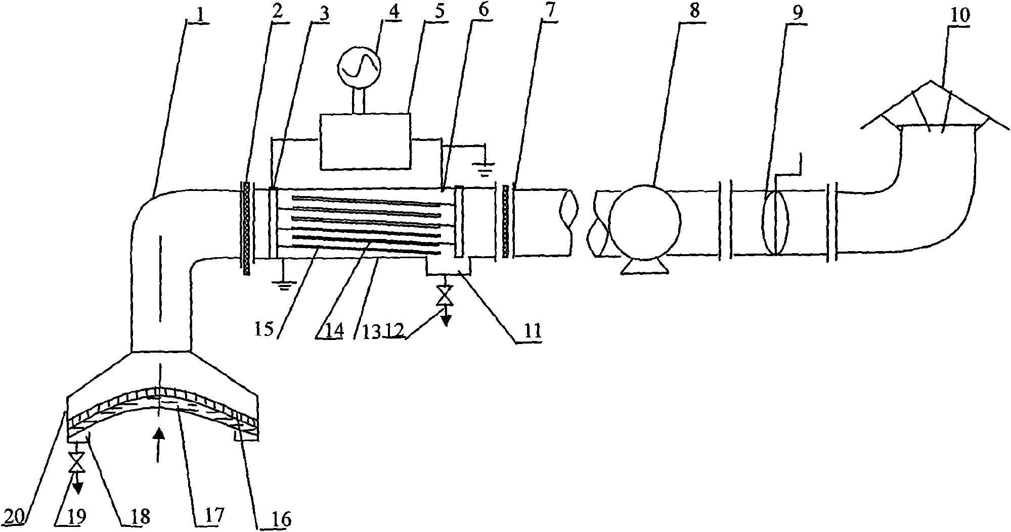
[0025] see figure 1 , Low-temperature plasma combined with surface modification filter membrane to purify cooking oil fume purifier includes gas collection hood 20, the top of gas collection hood 20 is connected to exhaust pipe through elbow 1, and rainproof cap 10 is installed at the outlet of exhaust pipe.

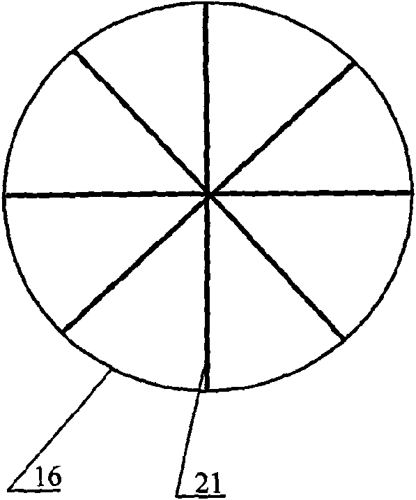
[0026] A stainless steel mesh 16 is installed on the working surface of the gas collecting hood 20, and the stainless steel mesh 16 is provided with a filter membrane 17, and the lower edge of the gas collecting hood 20 is inwardly folded to form a first-stage oil collecting tank case 18. The stainless steel net 16 is a radial net, and the inner surface of the net is equipped with a "rice" font stainless steel bar 21, see figure 2 This stainless steel mesh can both play a reinforcement effect, and can be used as the diversion mechanism of intercepting oil dirt again, the liquid oil dirt that makes filter membrane 17 surface intercepts can flow in the oil sump box 18 of ...

Embodiment 2

[0032] A pair of anode plates 15 and cathode plates 14 which are staggered and parallel to each other are installed in the secondary oil collection tank 13, and the material of the anode plates is aluminum.

[0033] Others are with embodiment 1.


PUM


Abstract

The invention relates to an oil and smoke purifier of a low-temperature plasma synergistic modified filtering membrane in purification catering. The oil and smoke purifier comprises a gas-collecting hood, a vent pipe and a fan, wherein a working surface of the gas-collecting hood is provided with a stainless steel mesh and a filtering membrane in sequence, and a trough-shaped oil-collecting tank is arranged at the lower edge of the working surface of the gas-collecting hood; a secondary oil-collecting tank is arranged on the vent pipe in series, more than one pair of anode plate and cathode plate which are parallel to each other are arranged in the secondary oil-collecting tank, and a high-pressure pulse plasma generator is arranged between an anode terminal and a cathode terminal in series; an oil outlet is arranged at one side of the bottom of the second oil-collecting tank; and a blast volume adjusting valve is arranged at an outlet of the vent pipe. The invention has the advantagesthat the synergistic effect between filtering materials and a plasma has unique advantages for removing flue gas in a kitchen; the structure is simple, the removal ratio is high, the maintenance is convenient, and the treated gas has no odors; and the device is unnecessary to be rinsed, belongs to a technology for purifying flue gas in the kitchen by adopting a dry method, and not only can be used for purifying oil and smoke in hotels, restaurants and dining halls, but also can be applied to gas purification of a large-size central air-conditioning system.

Description

technical field [0001] The invention relates to an oil fume purifier for the catering industry. Background technique [0002] The main components of kitchen fume are edible oil, seasoning, water vapor, and various harmful gas components produced by pyrolysis. The traditional kitchen exhaust gas treatment in our country is mainly the range hood. Although this method partially purifies the indoor air, many harmful substances in the lampblack are discharged into the atmosphere without treatment, which fails to achieve complete purification in the true sense and seriously damages the atmospheric environment. At the same time, it is extremely difficult to clean the sludge, smoke and other substances that adhere to the wall of the range hood and the exhaust fan. With the rapid development of my country's catering industry, especially in large-scale hotels, restaurants, canteens and other catering industries, the pollution of cooking fume is becoming more and more prominent. [0...

Claims


Application Information

Patent Timeline
IPC IPC(8): B01D50/00B01D39/16B03C3/017F24C15/20
Inventor 陈明功
Owner 陈明功
Learn More