A Radiographic Digital Imaging Inspection System for Circumferential Welds of Pressure Equipment

A technology of pressure-bearing equipment and digital imaging, which is applied in the use of radiation for material analysis, etc., can solve problems such as difficult to discard liquid medicine, large fluctuations in the influence of ambient temperature and magnetic field, and environmental pollution, so as to reduce the radiation dose and its scope of influence , significant economic and social benefits, and beneficial to environmental protection

Inactive Publication Date: 2012-02-01
CHINA SPECIAL EQUIP INSPECTION & RES INST
View PDF7 Cites 0 Cited by
  • Summary
  • Abstract
  • Description
  • Claims
  • Application Information

AI Technical Summary

Problems solved by technology

Film photography has the following disadvantages: 1. The detection process is complicated, and the detection time needs at least 20 to 30 minutes; 2. It is difficult to save and manage the film, and the waste liquid has environmental pollution; 3. It is impossible to realize batch detection and automatic interpretation of defects
Disadvantages of industrial TV: 1. There is edge distortion; 2. It is greatly fluctuated by the influence of ambient temperature and magnetic field; 3. The angle of collecting light is small, resulting in the loss of information; 4. The imaging quality cannot be compared with film photography
With the development of various rapid manufacturing technologies, the above detection methods are difficult to meet the needs of the actual manufacturing process and inspection market, which has restricted the development of special equipment manufacturing industry to a certain extent.

Method used


Image

  • A Radiographic Digital Imaging Inspection System for Circumferential Welds of Pressure Equipment
  • A Radiographic Digital Imaging Inspection System for Circumferential Welds of Pressure Equipment
  • A Radiographic Digital Imaging Inspection System for Circumferential Welds of Pressure Equipment

Examples


Embodiment Construction

[0016] In order to make the object, technical solution and advantages of the present invention clearer, the present invention will be described in further detail below in conjunction with the embodiments and accompanying drawings. Here, the exemplary embodiments and descriptions of the present invention are used to explain the present invention, but not to limit the present invention.

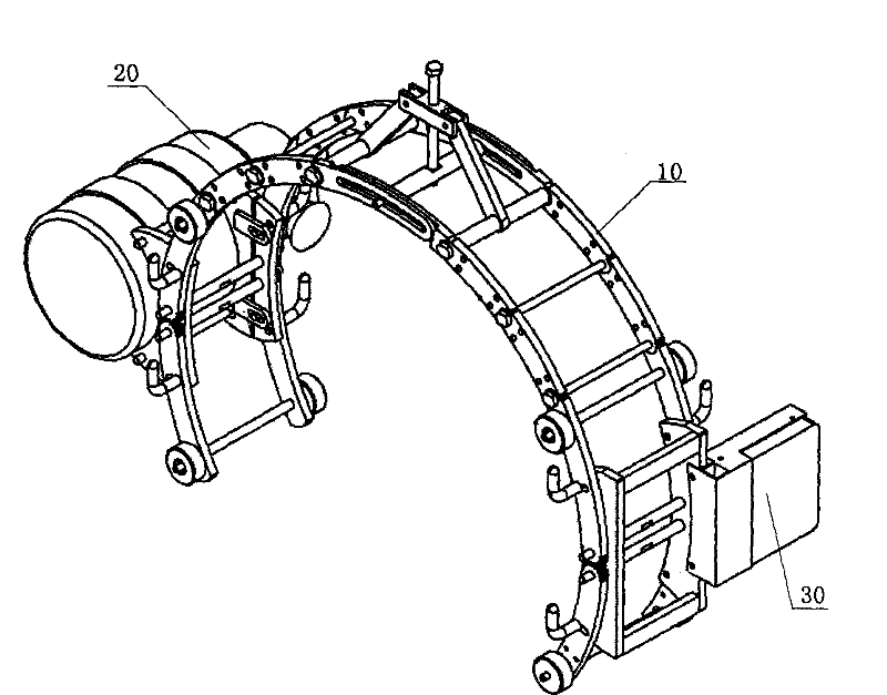
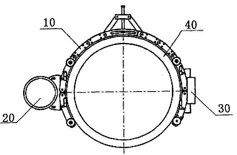
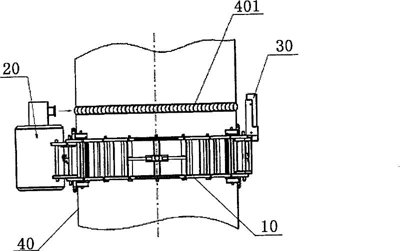
[0017] figure 1 It is a three-dimensional view of the radiography digital imaging detection system for the girth weld of the pressure equipment according to the embodiment of the present invention, Figure 2a for figure 1 main view of Figure 2b for figure 1 top view. The following combination Figure 1-Figure 2b Describe how the system works. The system includes: an automatic scanning device 10 for pressure-bearing equipment, which is arranged outside the pressure-bearing equipment 40, and is used to rotate around the axial direction of the pressure-bearing equipment 40; a ray emitting d...


PUM


Abstract

The invention provides a radiographic digital imaging detection system for girth welds of pressure equipment. The system includes: an automatic scanning device for pressure-bearing equipment, which is arranged on the outside of the pressure-bearing equipment, and is used to rotate around the axial direction of the pressure-bearing equipment; a ray emitting device, fixed on the pressure-bearing equipment for automatic scanning A device for emitting radiation to pass through the girth weld; a radiation receiving and image processing device, fixed on the automatic scanning device of the pressure-bearing equipment and arranged opposite to the radiation emitting device, for receiving the emitted radiation , converting the optical signal of the ray into a digital signal to generate a girth weld inspection image, and processing the image to generate a processing result. By changing the diameter of the automatic scanning device for pressure-bearing equipment, the present invention can realize the digital imaging detection of girth welds of pressure-bearing equipment with different diameters, which can not only greatly reduce the detection cost, shorten the product development cycle, but also quickly detect defects. identify.

Description

technical field [0001] The present invention relates to the technical field of radiographic detection and imaging, in particular to the field of non-destructive testing of pressure equipment, in particular to a radiographic digital imaging detection system for girth welds of pressure equipment, which can be widely used in girth welds of pressure equipment Non-destructive testing and non-destructive evaluation. Background technique [0002] Pressure equipment includes boilers, pressure vessels, pressure piping and other equipment. Boilers are composed of power station boilers and industrial boilers. Power station boilers are the "heart" of thermal power generation. Industrial boilers mainly provide heat energy for industrial (petroleum, chemical, fertilizer, metallurgy, papermaking, etc.) processes, and provide heating and heating for public and civil buildings. hot water. Therefore, the development of boiler equipment will directly affect the development of national econom...

Claims


Application Information

Patent Timeline
Patent Type & Authority Patents(China)
IPC IPC(8): G01N23/18
Inventor 丁克勤寿比南林树青梁丽红陈光张旭
Owner CHINA SPECIAL EQUIP INSPECTION & RES INST
Why Eureka
Try Eureka