
Power taking method for large-current high-voltage transmission bus

A power transmission bus and high-current technology, which is applied in the field of high-current and high-voltage power transmission bus, can solve the problems of volume and installation constraints, inability to work with instruments and devices, and poor high-temperature resistance of rechargeable batteries, and achieve simple structure and installation , save the cost of installation materials, good effect of explosion-proof sealing performance

Inactive Publication Date: 2011-08-24
HANGZHOU CTRLYARE ELECTRONICS
View PDF0 Cites 0 Cited by
  • Summary
  • Abstract
  • Description
  • Claims
  • Application Information

AI Technical Summary

Problems solved by technology

When the battery is used for power supply, since the high-voltage environment of the power equipment is relatively closed, the power cannot be cut off at will, so the use of disposable batteries cannot be replaced in time when the batteries are exhausted, and the rechargeable batteries cannot be replaced at all because of their poor high temperature resistance. Applicable to enclosed high current heating space
When adopting the capacitor step-down method for power supply, it is first necessary to make a large insulator outside the capacitor. Such a huge volume cannot be realized in power equipment that requires very strict volume and insulation distance. The device generally can only generate a current of about 200uA, which cannot make general instruments and devices work
When the CT power supply method is used for power supply, although a relatively stable power supply can be obtained, the volume and installation are also greatly restricted; at the same time, the iron core as the core of the CT must be surrounded by a high-voltage and high-current transmission line (referred to as the busbar) when working. , the huge size of the iron core will cause safety accidents in many small spaces, and the manufacture of the iron core must be customized according to different high-voltage equipment, and molds need to be made during production, which has a long cycle, high cost, and very inconvenient application
When the photoelectric method is used for power supply, the volume, precision and complexity of the instrument and the cost of measurement and control instrument equipment are increased due to the use of ground laser emitting devices, optical fiber cables for laser transmission, photoelectric cell arrays for photoelectric conversion, optical refraction and concentrating systems, etc. , and the electric energy converted at the same time is very limited; moreover, the climbing and binding of optical fibers will bring many hidden dangers in the layout, insulation and safety of power transmission lines
[0004] Therefore, these traditional power supply methods have major defects and fatal weaknesses, which also greatly restrict the application of such equipment

Method used


Image

  • Power taking method for large-current high-voltage transmission bus
  • Power taking method for large-current high-voltage transmission bus
  • Power taking method for large-current high-voltage transmission bus

Examples


Embodiment Construction

[0036] The technical scheme of the present invention is described below in conjunction with accompanying drawing and embodiment:

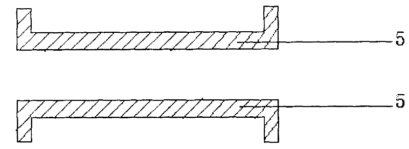
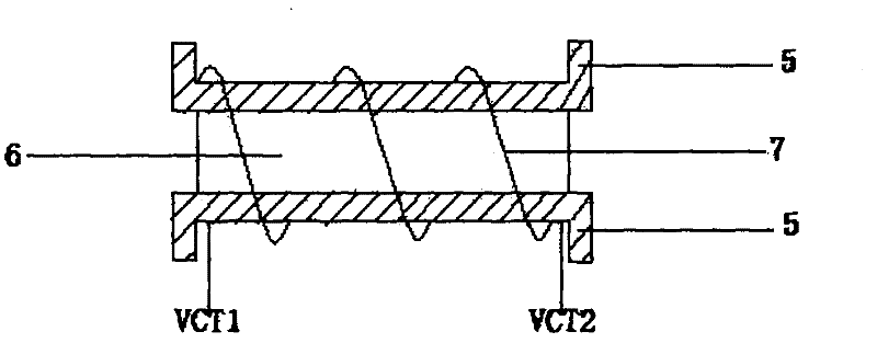
[0037] figure 1 It is a longitudinal section schematic diagram of the magnetic induction coil frame 5, and the magnetic induction coil frame 5 is made of polytetrafluoroethylene. figure 2 It is a schematic diagram of the structure of the magnetic induction coil, in which the silver-plated copper wire 7 is wound on the coil frame 5, and the powder of magnetic iron oxide powder is compacted and packaged inside the coil frame 5 to form the iron core 6, VCT1, VCT2 Connected to the filter circuit as wiring. As preferably, the length of the bobbin 5 is 60mm, the diameter is 15mm, and the wall thickness is 1mm. The diameter of the silver-plated copper wire 7 is 2mm and is wound on the bobbin 5 at intervals of 1mm. The magnetic iron oxide The specification of the powder is 2000 mesh, and the inside of the coil frame 5 is sealed with 502 glue drops. In ...


PUM


Abstract

The invention discloses a power taking method for a large-current high-voltage transmission bus. A position in a secondary low-voltage equipment shell distancing from the high-voltage transmission bus by 2 to 5 mm is provided with a magnetic induction coil. The magnetic induction coil consists of a coil framework, an iron core and a silver-plated copper wire, wherein the coil framework is made ofa polytetrafluoroethylene material; the iron core is formed by tamping magnetic iron oxide powder with the size not less than 2,000 mesh and packaging the magnetic iron oxide powder into the coil framework; and the silver-plated copper wire is wound onto the coil framework. The secondary low-voltage equipment is fixed on the high-voltage transmission bus then. When the bus is loaded and the magnetic induction coil generates an induction current, the bus supplies power for the secondary low-voltage equipment after matching with a filter circuit, a voltage dropping and voltage stabilizing circuit and a combined power switching circuit to form a constant-voltage constant-current power supply. The power taking method can take power between 30 and 240mA and meets the power requirements of the secondary low-voltage equipment under the environment of high voltage and large current.

Description

technical field [0001] The invention relates to the field of high-voltage electricity extraction, in particular to an electricity extraction method for a high-current high-voltage power transmission bus. Background technique [0002] With the improvement of the degree of automation of power equipment, in the environment of primary high voltage and high current, more and more secondary low-voltage equipment, such as instruments and meters, data acquisition, transmitters, sensitive devices, etc., appear, and these low-voltage equipment must be normal The work is inseparable from the low-voltage power supply. According to the safety requirements of the power industry, it is absolutely not allowed to carry or connect any electrical signal wires between the high-voltage environment and the low-voltage environment. Therefore, powering these low-voltage devices without an external power supply has become the biggest problem in the application of such products. [0003] At present,...

Claims


Application Information

Patent Timeline
Patent Type & Authority Patents(China)
IPC IPC(8): H02J17/00H02J5/00
Inventor 简浩
Owner HANGZHOU CTRLYARE ELECTRONICS
Learn More