
Portable wireless laser communication terminal machine

A wireless laser, communication terminal technology, applied in the field of communication, can solve the problems of inconvenience for single person to carry and use, increase the size and weight of the communication terminal, and achieve portable size and weight, satisfactory volume and weight, and overcome hand-held jitter. Effect

Active Publication Date: 2010-02-24
HUBEI JIUZHIYANG INFRARED SYST CO LTD
View PDF3 Cites 19 Cited by
  • Summary
  • Abstract
  • Description
  • Claims
  • Application Information

AI Technical Summary

Problems solved by technology

The disadvantages of the above-mentioned schemes are that a separate aiming channel needs to be provided to achieve precise beam alignment, and a platform stabilization system is required to obtain a longer communication distance (greater than 2km), resulting in the size and size of the communication terminal. Increased weight makes it inconvenient to be carried by a single person

Method used


Image

  • Portable wireless laser communication terminal machine
  • Portable wireless laser communication terminal machine

Examples


Embodiment 1

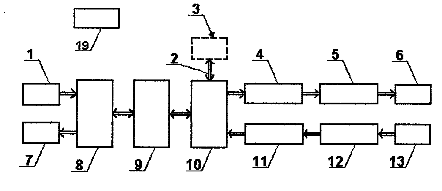
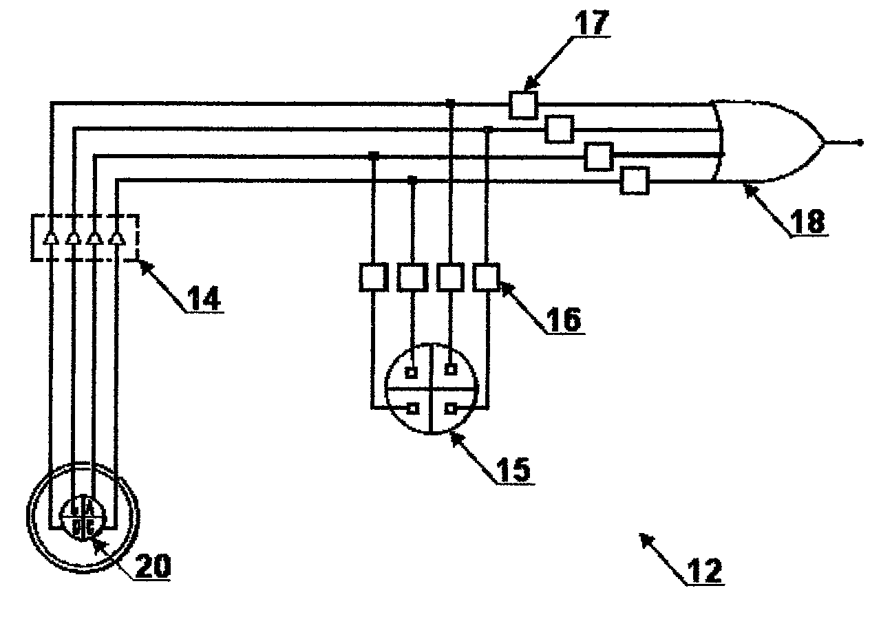
[0025] Embodiment 1: as figure 1 , figure 2 As shown, a portable wireless laser communication terminal, it has an audio voltage / power amplifier 8, a codec 9, a microcontroller 10, a modulation drive circuit 4, a semiconductor laser 5, and a transmitting optical system 6 connected in order of signal processing , the audio voltage / power amplifier 8 integrates an audio voltage amplifier and a power amplifier, respectively amplifies the voltage of the input audio signal and amplifies the power of the decoded signal, and the codec 9 implements digital encoding for the amplified analog signal, digital encoding The methods can be divided into pulse code modulation PCM, parametric code modulation and hybrid code modulation. When pulse code modulation is used, the encoder is required to support a sampling frequency of 8k / s and above, 8bit digital encoding, and a data rate of 64kbps; parametric code modulation is used Or when mixed coding and modulation, because it is a compression co...

Embodiment 2

[0026] Embodiment 2: What is different from Embodiment 1 is: the semiconductor laser 5 is a GaAs pulsed semiconductor laser, and its laser wavelength is 1550nm; the selected value of the divergence angle after the beam collimation of the emitting optical system 6 to the semiconductor laser 5 is 10°; The detector is an InGaAs four-quadrant detector.

Embodiment 3

[0027] Embodiment 3: Different from Embodiment 1: the laser wavelength of the semiconductor laser 5 is 1600nm; the divergence angle selected by the emission optical system 6 to the beam collimated by the semiconductor laser 5 is 5 °; the detector is a silicon four-quadrant detection device.


PUM


Abstract

The invention relates to a portable wireless laser communication terminal machine which belongs to the technical field of communication. The portable wireless laser communication terminal machine comprises a pickup, a sound reproducer, an audio-frequency voltage / power amplifier, a coder-decoder, a microcontroller, a modulation drive circuit, a semiconductor laser, an emission optical system and asignal back-end processing circuit, wherein the signal back-end processing circuit is sequentially connected with a photoelectric detector, a front-end processing circuit and a receiving optical system; the semiconductor laser is a pulse semiconductor laser; the emission optical system collimates light beams emitted by the semiconductor laser, and the value selection range of the divergence angleof the collimated light beams is greater than or equal to 1.5 degrees and smaller than or equal to 12 degrees; and the photoelectric detector and the front-end processing circuit are provided with silicon four-quadrant detectors or indium-gallium-arsenic four-quadrant detectors. The invention realizes signal optical detection and collimation integration, does not need an independent collimation passage for accurately collimating the light beams, does not need an independent beacon optical tracking system and a stabilized platform and enables the volume and the weight of the terminal machine tomeet the portable requirement.

Description

technical field [0001] The invention relates to a portable wireless laser communication terminal, which belongs to the technical field of communication, and is a portable wireless laser communication terminal using the atmosphere as a channel and laser as a carrier. Background technique [0002] Laser communication uses laser as the carrier to transmit information such as voice, image and data. Compared with microwave, laser has the characteristics of short wavelength, high coherence and spatial orientation. Therefore, it determines the outstanding advantages of laser communication: large communication capacity, low power consumption, small size, light weight, high confidentiality, strong resistance electromagnetic interference. Compared with optical fiber communication, wireless laser communication has the advantages of low cost, convenient deployment, and convenient emergency communication. Therefore, since the 1970s, wireless laser communication has attracted more and mo...

Claims


Application Information

Patent Timeline
Patent Type & Authority Applications(China)
IPC IPC(8): H04B10/10H04B10/11
Inventor 孙峰张鑫陈伟高凡邓代竹
Owner HUBEI JIUZHIYANG INFRARED SYST CO LTD
Learn More