Hot air circulating heating insulation device and method for using same

A heating and heat preservation, hot air circulation technology, applied in heating devices, applications, household appliances, etc., can solve the problems of energy consumption, poor operability and controllability, waste of fuel, etc., to reduce energy use loss, temperature The adjustment is convenient and fast, and the effect of reducing energy consumption

Inactive Publication Date: 2010-03-03
倪军
View PDF0 Cites 26 Cited by
  • Summary
  • Abstract
  • Description
  • Claims
  • Application Information

AI Technical Summary

Problems solved by technology

[0010] 1. There is no own heating and heat preservation environment, the heating and heat preservation environment is completely open, the heating and heat preservation environment is obtained by consuming a lot of energy, and the heat dissipation is very fast
This is the biggest bad factor of wasting energy
[0011] 2. The energy absorption ratio is very low. In many cases, the object to be processed only needs to be heated to a temperature in principle. At this time, the heat energy absorption of the object to be processed has reached the minimum, and only a relatively stable temperature is required. environment, when the processed object reaches the processing temperature, it no longer absorbs heat, but in order to ensure the temperature of the processed object, a large amount of energy output is still required to maintain the temperature environment
[0012] 3. In the steaming mode, a large amount of water is heated to form steam, the steam generates a large amount of gas expansion, and a large amount of high-energy steam is discharged, forming the main energy consumptio

Method used


Image

  • Hot air circulating heating insulation device and method for using same
  • Hot air circulating heating insulation device and method for using same
  • Hot air circulating heating insulation device and method for using same

Examples


Embodiment 1

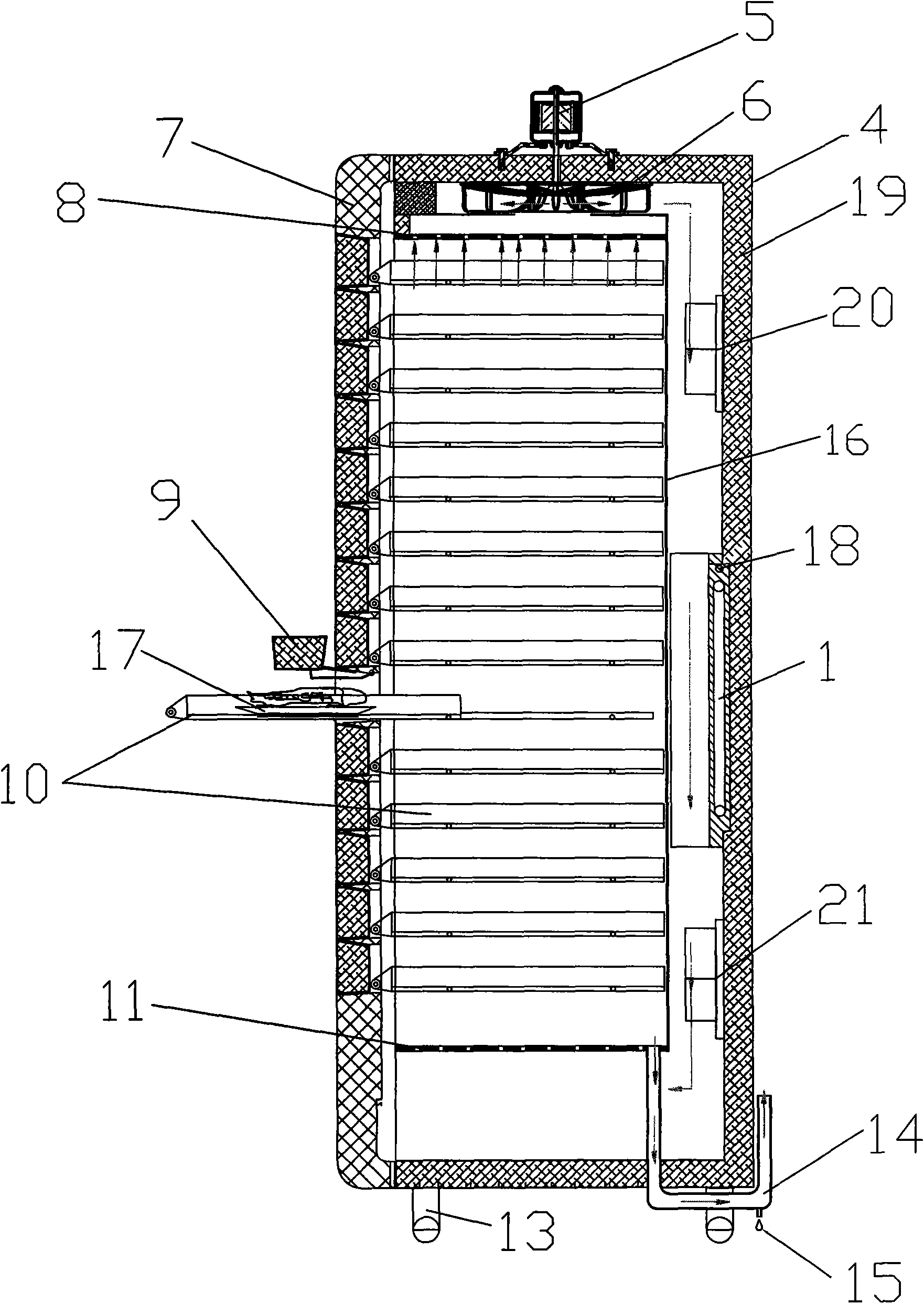
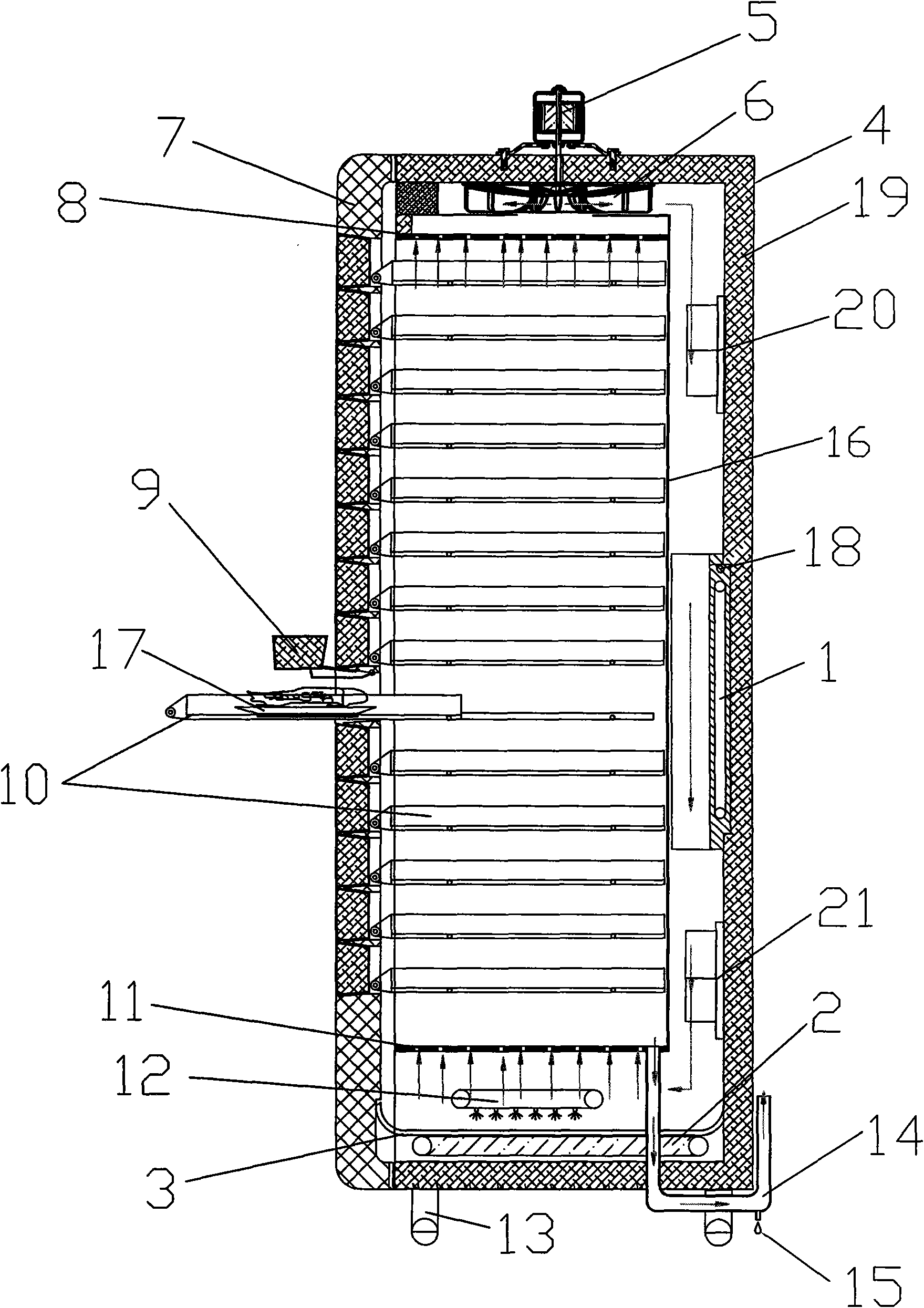
[0070] Example 1, see figure 1 . The device of the present embodiment comprises a casing 4 with an insulating layer 19, a casing door 7 and an electric heating device 1; Appropriate gaps are left on the top board, the bottom board and the rear wall respectively, and multiple layers of mutually parallel drawable cages 10 are arranged in the inner box 16; the top board and the bottom board of the inner box 16 are respectively a The uniform gas partition 8,11;

[0071] Open the mouth corresponding to the cage 10 on said box door 7, and arrange the unit door 9 with insulation layer on the mouth; In addition: a circulation fan 6, this circulation fan 6 is contained in the inner box 16 and In the space between the top plates of the box body 4, its drive motor 5 can be installed outside the top of the box body 4;

[0072] Above-mentioned electric heater 1 is a gas heater, and this gas heater is contained in the space between inner box 16 and the rear wall of casing 4, and this sp...

Embodiment 2

[0076] Example 2, see Figure 4 . In order to realize the automation of the device, a control device can also be added on the basis of the above-mentioned scheme, and the circuit of the control device includes:

[0077] One CPU25, this CPU25 is connected with CPU power supply 23, input, output interface circuit 24, analog-to-digital converter 28, clock oscillating circuit 26 and keyboard 27 respectively; Fan controller 6.1, gas heating controller 1.1, steam heating controller 2.1, water mist controller 211.1 are connected and powered; input and output interface circuit 24 is connected with fan controller 6.1 and fan 6, gas heating controller 1.1 and Gas heater 1, steam heating plate controller 2.1 and steam heating plate 2 are connected with water mist controller 211.1 and water mist electromagnetic switch 211, and are connected to control mains power supply to expand various protection circuits; analog-to-digital converter 28 It is respectively connected with two temperatur...

Embodiment 3

[0078] Embodiment 3, see Figure 5 . The method for using the device of the above-mentioned embodiment comprises the following steps:

[0079] Step 01: Turn on the power;

[0080] Step 02: Start the circulation fan;

[0081] Step 03: Start the gas heater;

[0082] Step 04: Measure the temperature of the lower part of the box body by the temperature and humidity sensor 21; if the temperature does not reach the set temperature, then adjust the heating power of the gas heater again for further heating;

[0083] Step 05: Measure the temperature of the upper part of the box by the temperature and humidity sensor 20; if the set temperature is not reached, start the gas heater again for further heating; if the set temperature is reached, proceed to the next step;

[0084] Step 06: Stop gas heating and continue to keep warm;

[0085] Step 07: Finishing.

[0086] After the power is turned on, the gas heater 1 and the circulating fan 6 start to work; the hot gas moves upwards thro...


PUM


Abstract

The invention discloses a hot air circulating heating insulation device and a method for using the same, which aim to solve the problems of energy waste and inconvenient operation of the prior device.The insulation device comprises a box body with an insulating layer, a box door and an electric heater, and is characterized in that: the inside of the box body is also provided with an inner box, acirculating fan, two temperature and humidity sensors and an exhaust pipe, wherein the inner box has a proper gap with a top plate, a bottom plate and a back wall of the box body respectively, a plurality of layers of withdrawable cage lattices mutually parallel to each other are arranged in the inner box, the top plate and the bottom plate are an air balancing baffle plate respectively, and unitdoors mutually corresponding to the cage lattices are arranged in the box door; the circulating fan is arranged in the gap between the inner box and the top plate of the box body; the electric heateris an air heater, and is arranged in the gap between the inner box and the back wall of the box body; one temperature and humidity sensor is arranged at the upper part of the back wall in the box body, and the other one is arranged at the lower part of the back wall in the box body; and the exhaust pipe is U-shaped, and one end of the exhaust pipe is communicated with the bottom of the inner box,while the other end penetrates out of the bottom plate of the box body to be communicated with the atmosphere.

Description

technical field [0001] The invention relates to a heating device, in particular to a heating insulation box used for energy saving in daily life and a usage method thereof. Background technique [0002] At present, with the increase of population and the development of social economy, the contradiction between supply and demand in various aspects is becoming increasingly prominent, especially in energy. The earth's energy resources continue to decrease, causing energy prices to rise year by year, and it also has a non-negligible impact on people's lives. [0003] Among people's living energy consumption, at least 40-50% of the living energy is used in the kitchen, including refrigerators and various frying, boiling and baking utensils. High-quality life has led to the popularization of automated appliances and high energy consumption. The energy-saving transformation of thermal processing equipment is of great significance to energy conservation. [0004] With the develop...

Claims


Application Information

Patent Timeline
IPC IPC(8): A47J27/04A47J27/16A47J27/00A47J36/24
Inventor 倪军
Owner 倪军
Why Eureka
Try Eureka