Heat-radiating substrate for alternating current LED light source

A technology of LED light source and heat dissipation substrate, which is applied in the field of heat dissipation substrate structure for AC LED light source, can solve the problems of performance and structure that cannot meet the requirements, decline in heat conduction and heat dissipation performance, and increased LED light attenuation, so as to improve electronic compatibility and expansion Small variation and excellent heat dissipation effect

Inactive Publication Date: 2010-03-03
NANJING HANDSON SCI & TECH CORP
View PDF0 Cites 13 Cited by
  • Summary
  • Abstract
  • Description
  • Claims
  • Application Information

AI Technical Summary

Problems solved by technology

Gold and silver have better thermal conductivity, but the disadvantage is that the price is too high
The heat dissipation effect of pure copper is second, but in addition to the high cost, the copper sheet is heavy and not resistant to corrosion. Once the copper is oxidized, its thermal conductivity and heat dissipation performance will be greatly reduced, resulting in high temperature and increasing the LED failure. Possibility, resulting in increased LED light decay and shortened life
[0003] At this stage, one disadvantage of AC LED light sources is the risk of electric shock. For high voltages (that is, AC vo

Method used


Image

  • Heat-radiating substrate for alternating current LED light source
  • Heat-radiating substrate for alternating current LED light source
  • Heat-radiating substrate for alternating current LED light source

Examples


Embodiment 1

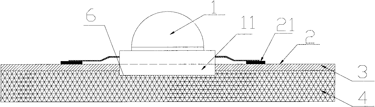
[0024] Such as figure 1 It can be seen from the structural schematic diagram of the heat dissipation substrate for LED light source of the present invention that the present invention designs and provides a heat dissipation substrate for AC LED light source with graphite as the heat dissipation seat layer. The basic structure of the heat dissipation substrate is divided into three layers, such as figure 1 As shown, it includes an LED light source 1 , a conductive layer 2 , an insulating layer 3 and a bottom layer 4 . Wherein conductive lines and power electrode pads 21 are distributed on the conductive layer 2 . The insulating medium of the intermediate insulating layer 3 generally adopts a high thermal conductivity epoxy glass fiber cloth bonding sheet or a special high thermal conductivity epoxy resin polymer; the thermal resistance is small, the bonding performance is excellent, it has the ability to resist thermal aging, and can withstand mechanical and thermal stress. ...

Embodiment 2

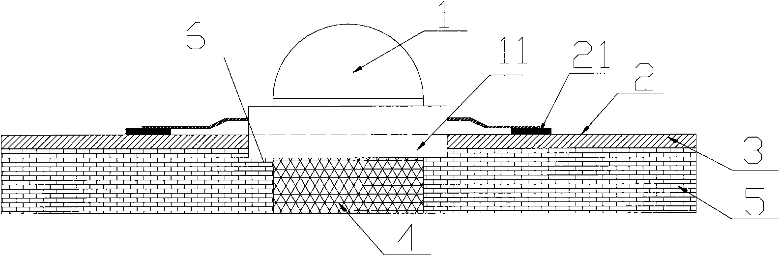
[0030] Such as figure 2 Shown is another structural combination of the heat dissipation substrate structure for the above-mentioned AC LED light source. This substrate structure can use graphite as a heat-conducting material and be embedded in other metal-based or non-metal-based heat-conducting substrates 5 to form a hybrid heat-conducting structure. The seat layer, the graphite layer is located directly below the heat sink of the LED light source 1, and the graphite wall is fully in contact with the through hole wall of other metal-based or non-metal-based heat-conducting substrate 5, and the heat is evenly transmitted along the two side walls. Two-dimensional plane to achieve the purpose of heat dissipation.

Embodiment 3

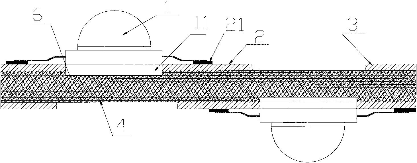
[0032] In addition to the above substrate structure with a single conductive layer, the structure of the heat dissipation substrate for an AC LED light source of the present invention can also be double-sided, and a conductive layer and an LED light source can also be provided under the bottom layer.

[0033] Such as image 3 What is shown is another structural combination of the heat dissipation substrate structure for the above-mentioned AC LED light source. The substrate structure is similar to the first embodiment, and both use graphite layer 4 as the seat layer of the heat dissipation substrate. The difference is that the fixing groove 6 , insulating layer 3 , conductive layer 2 and LED light source are arranged on the other side of the graphite layer in dislocation relative to the LED light source on the upper layer. The dislocation formed makes the graphite layer on the other side of the heat dissipation substrate corresponding to each LED light source exposed, so that ...


PUM

PropertyMeasurementUnit
Thicknessaaaaaaaaaa
Thicknessaaaaaaaaaa

Abstract

The invention discloses a heat-radiating substrate for an alternating current LED light source, which comprises a bottom layer, an insulating layer which is arranged on the bottom layer and can bear mechanical and thermal stress, a conductive layer which is arranged on the insulating layer and distributed with a conductive circuit and an electrode pad, and the LED light source embedded in a fixedslot of the heat-radiating substrate. The heat-radiating substrate is characterized in that the bottom layer is a graphite layer with size stability and heat radiation, or when the bottom layer is made of the conventional thermal conductive base materials, the graphite layer is embedded in the bottom layer which is positioned under a heat sink of the LED light source, the heat sink of the LED light source penetrates the bottom of the fixed slot and is in contact with the surface of the graphite layer, and the periphery of the heat sink is bonded with insulating media of the insulating layer, thereby constituting the heat-radiating substrate with the three-layer structure. The heat-radiating substrate can effectively solve the thermal conductive performance, the electrical insulating performance and the mechanical processing performance of a printed circuit board, thereby being widely applied in heat transfer media of electronic devices and improving the working stability.

Description

technical field [0001] The invention relates to a printed circuit board, in particular to a heat dissipation substrate structure for an AC LED light source, and belongs to the technical field of printed circuit boards. Background technique [0002] In the development of packaging technology, function improvement and miniaturization have resulted in higher and higher heat density. Some LED products cannot dissipate enough heat only by packaging design, and the heat dissipation function must be enhanced by PCB design. At present, the heat sink substrates used in general heat dissipation materials (such as civilian high-end electronic devices, LED chip materials, heat exchangers for industrial equipment, etc.) are almost all aluminum alloys, but aluminum is not the metal with the highest thermal conductivity. Gold and silver have better thermal conductivity, but the disadvantage is that the price is too high. The heat dissipation effect of pure copper is second, but in additio...

Claims


Application Information

Patent Timeline
IPC IPC(8): F21V19/00F21V29/00F21V23/00H01L23/373F21Y101/02
Inventor 孙建国
Owner NANJING HANDSON SCI & TECH CORP
Why Eureka
Try Eureka