Controllable reactor with air gap

A reactor and gas-carrying technology, which is applied in variable inductors, inductors, variable transformers, etc., can solve the problems of increased loss, saturation nonlinearity, large value, etc., and achieve the effect of reducing loss

Inactive Publication Date: 2010-03-03
刘有斌
View PDF7 Cites 16 Cited by
  • Summary
  • Abstract
  • Description
  • Claims
  • Application Information

AI Technical Summary

Problems solved by technology

The controllable reactor is developed on the basis of the magnetic amplifier. The main disadvantage of the magnetically saturated reactor is: the change of the control DC will cause the change of the internal current of the triangular coil, and the transition process time depends on the time constant of the triangular coil. The larger the value, the slower the response time and cannot meet the needs of fast adjustment; in addition, the effective material consumption (3.0kg / kVA) and active power loss (1.0%) are relatively large, and the effective material consumption of the generally uncontrollable iron core reactor and active power loss are only 0.8kg / kVA and 0.5% respectively
[0004] The working principle of the above-mentioned controllable reactor is actually the phenomenon that the reluctance increases when the iron core of the reactor is saturated. The biggest problem caused by the saturation of the iron core is that the saturation is nonlinear, so it has many problems in use. Large harmonics will pollute the system, and saturation will inevitably lead to increased losses
The magnetic valve type or magnetically controlled controllable reactor cannot be used in filtering occasions because of its own harmonics, although the capacity can be adjusted.

Method used


Image

  • Controllable reactor with air gap
  • Controllable reactor with air gap

Examples


Embodiment Construction

[0016] The present invention will be further described below in conjunction with the accompanying drawings.

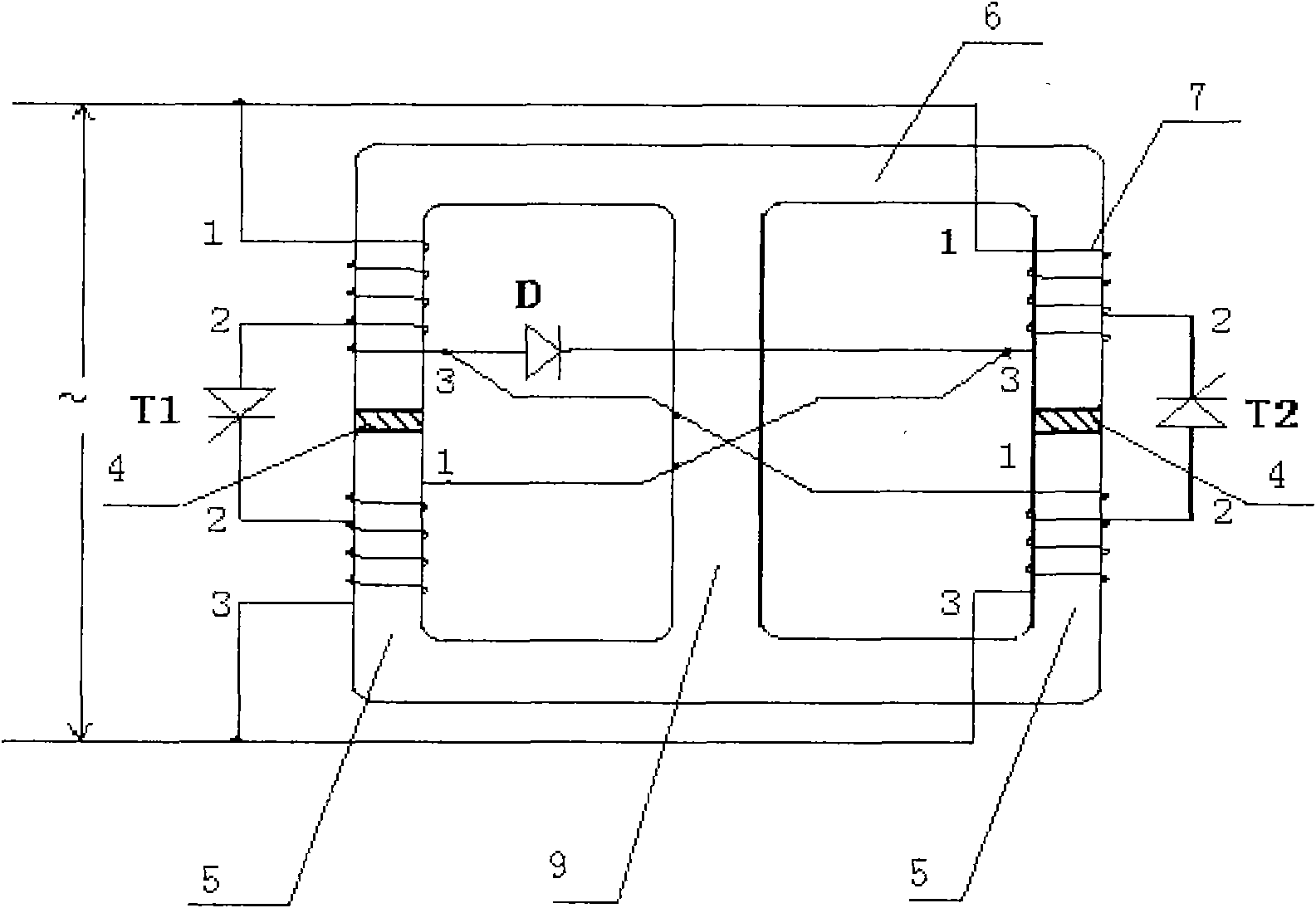
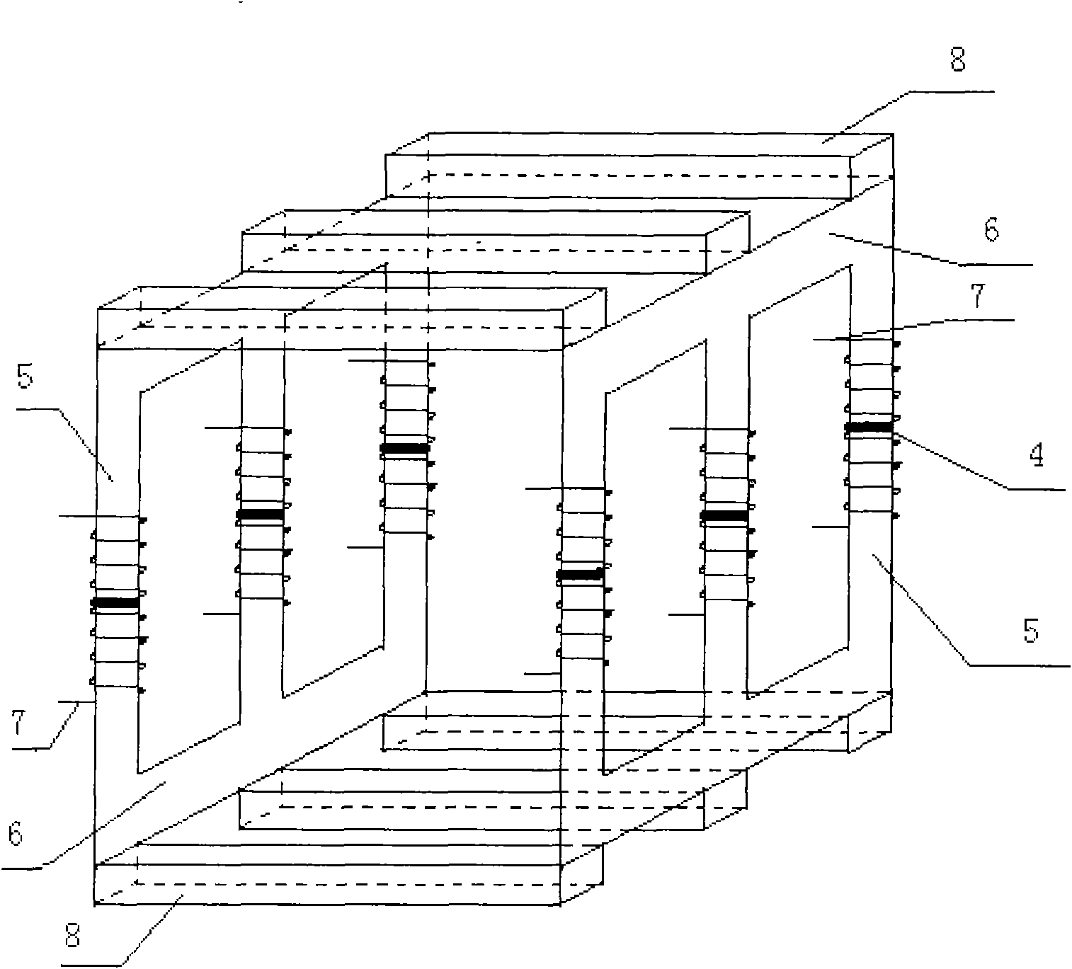
[0017] Each split iron core column of the controllable reactor with air gap has one or more groups of air gap layers 4 , the structure and process of the air gap layer are the same as those of common fixed capacity reactor with iron core. Each split column is also equipped with two windings with middle taps. The four windings are respectively called upper left, lower left, upper right, and lower right. The numbers of the three outlets of each winding are 1, 2, and 3. The upper outlet, 3 is the lower outlet, 2 is the middle tap, there are 12 outlets in total. Among them, the upper left 1 is connected with the upper right 1, the lower left 3 is connected with the lower right 3, and are respectively connected to the two ends of the single-phase AC power supply. The upper left 3 is connected to the lower right 1, and connected to the anode of the freewheeling diode. The ...


PUM


Abstract

Aiming at the problems that the capacity of reactive power provided by an electrical network is not continuously adjustable, or the capacity is continuously adjustable, but larger harmonic wave exists, the invention adopts a novel controllable reactor with an air gap, wherein the capacity of the reactor is continuously adjustable, but the harmonic wave does not exist. The controllable reactor comprises a reactor body and a driving control circuit, a non-magnetic air gap layer is arranged on an iron core of the reactor, and linear relationship exists between the magnetic flux density B and themagnetic field intensity H in the air gap field, therefore, the harmonic wave does not basically exist in the current of the controllable reactor with the air gap; a three-iron-core column structure is adopted when the reactor is a single-phase reactor, and a six-iron-core column structure is adopted when the reactor is a three-phase reactor; the controllable reactor not only can be used for beingconnected with a reactor in parallel, but also can be used for being connected with a reactor in series; and when the controllable reactor is connected with the reactor in series, the filtering frequency can be changed on line by adjusting the tuning frequency points of the reactor and the capacitors connected in series, therefore, the online automatic filtering becomes possible.

Description

Technical field [0001] The invention is a new type of electrical equipment for providing reactive power in the grid. Background technique [0002] The most important method used for reactive power compensation in the power system is to switch capacitors. The switching capacity is not continuously adjustable, especially in the high-voltage field. Because of the high cost, the series of capacitor switching Rarely, the control accuracy of reactive power is almost no, and the switching capacitor also produces a large inrush current, which brings great inconvenience to its practical application. The currently used device that can continuously adjust the reactive capacity is the static var compensator (SVC). The voltage level of its controller is the same as the voltage level of the reactor, which is expensive and uses a thyristor to generate a large Harmonic, you need to add another set of filters to filter out the harmonics. In short, it occupies a large area, the control is ve...

Claims


Application Information

Patent Timeline
Patent Type & Authority Applications(China)
IPC IPC(8): H01F29/02H01F27/24H01F3/14H01F41/02H02J3/18
CPCY02E40/30
Inventor 刘有斌
Owner 刘有斌
Why Eureka
Try Eureka