Control method of permanent magnetic bearing-free permanent magnetic synchronous motor non-radial displacement transducer

A radial displacement, synchronous motor technology, used in motor generator control, electronic commutation motor control, electronic commutator and other directions, can solve the disadvantages of bearingless motor miniaturization, high power, high speed development, signal accuracy and Poor stability, expensive displacement sensor, etc.

Inactive Publication Date: 2010-03-10
SHANGHAI UNIV
View PDF0 Cites 19 Cited by
  • Summary
  • Abstract
  • Description
  • Claims
  • Application Information

AI Technical Summary

Problems solved by technology

[0003] (1) Since the radial displacement of the rotor detected by the sensor is actually the displacement value at the end of the motor, rather than the displacement value of the rotor under the stator winding of the motor, it will inevitably bring errors to the suspension control of the motor;
[0004] (2) The installation and debugging of the position sensor is very inconvenient
[0005] (3) The use of displacement sensors requires a test disk to be installed on the motor shaft, which actually increases the axial length of the motor and increases the volume of the system, which is not conducive to the development of bearingless motors in the direction of miniaturization, high power, and high speed;
[0006] (4) Sensor detection is susceptible to interference from the external environment, and the measurement accuracy of different sensors is affected to varying degrees by factors such as temperature drift, electromagnetic field, mechanical vibration, dust, etc., thereby reducing the reliability of the system;
[0007] (5) The high-precision displacement sensor itself is expensive, and the signal measured by the sensor requires an additional hardware conditioning circuit, which increases the cost of the system
[0009] The current radial displacement sensor technology for bearingless motors mainly uses the excitation signal injection method, using the mutual inductance between the motor torque control winding and the suspension winding, or the relationship between the self-inductance and displacement of the suspension winding, and detecting the difference between the two ends of the winding. Dynamic voltage is used to estimate radial displacement, which requires additional signal extraction and filtering hardware circuits, and the signal accuracy and stability are poor

Method used


Image

  • Control method of permanent magnetic bearing-free permanent magnetic synchronous motor non-radial displacement transducer
  • Control method of permanent magnetic bearing-free permanent magnetic synchronous motor non-radial displacement transducer
  • Control method of permanent magnetic bearing-free permanent magnetic synchronous motor non-radial displacement transducer

Examples


Embodiment Construction

[0033] A preferred embodiment of the present invention is described as follows in conjunction with accompanying drawing:

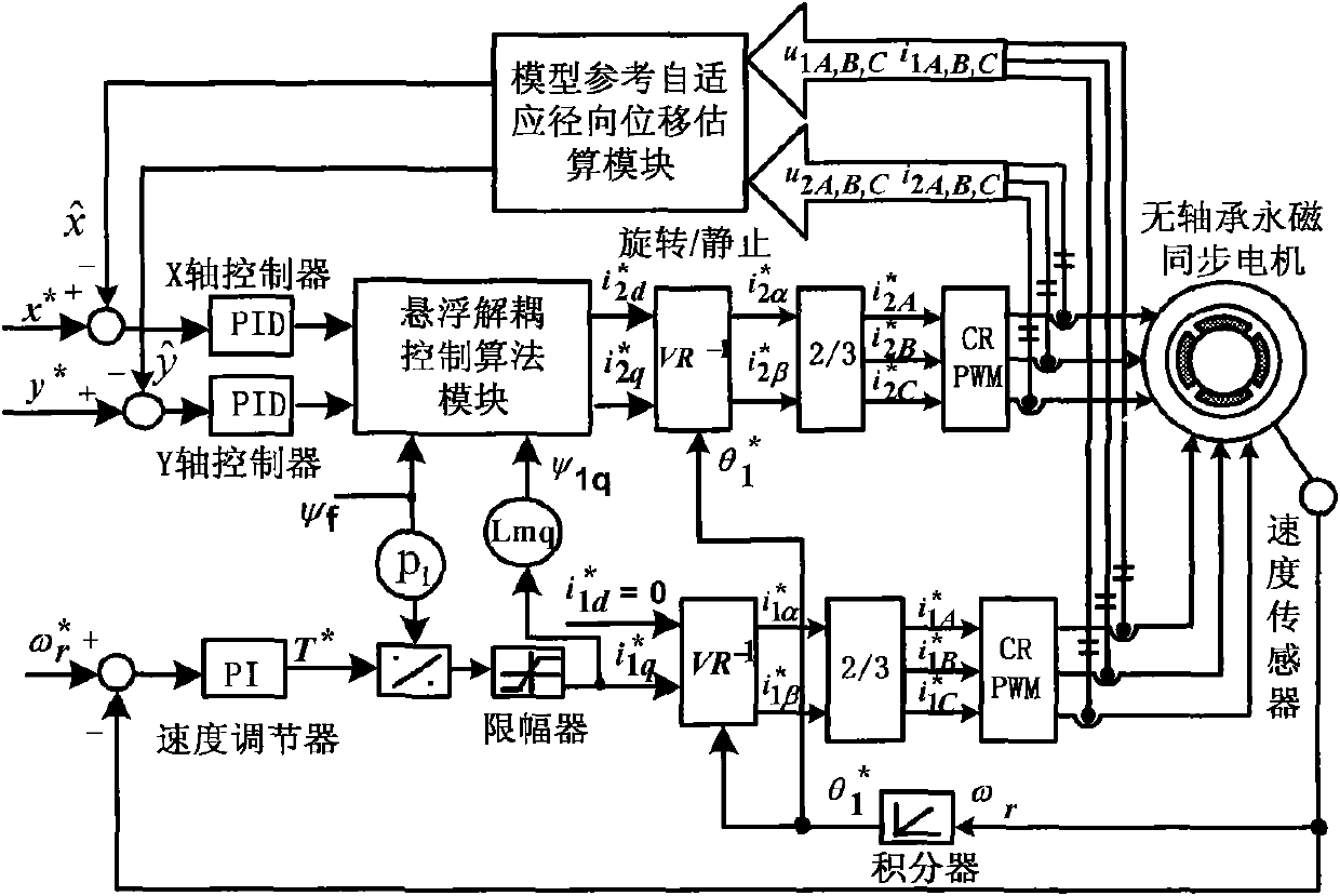
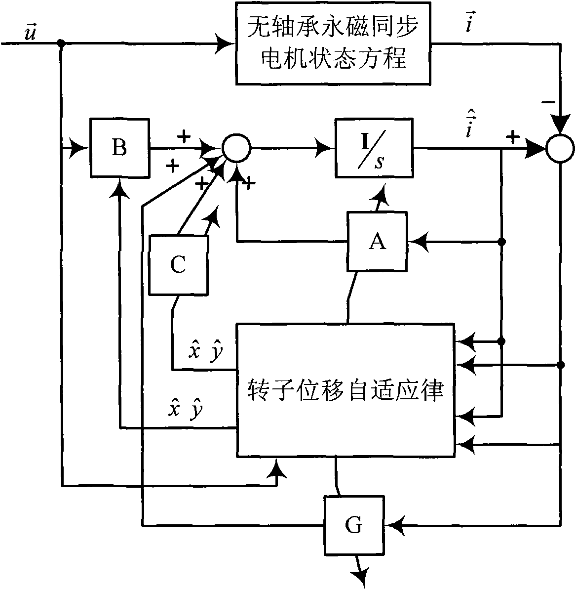
[0034] Such as figure 1 As shown, the permanent magnet bearingless synchronous motor without radial displacement sensor control method, by detecting the three-phase voltage and current of the torque control winding and the suspension control winding, using the model reference self-adaptive principle, constructing a model reference self-adaptive radial Displacement estimation module, the radial displacement of the rotor is estimated by the model reference adaptive radial displacement estimation module and and the displacement signal and Respectively with the reference displacement signal x of the given permanent magnet bearingless motor rotor * and y* For comparison, the given suspension force F of the x-axis and y-axis are respectively obtained after adjustment by the displacement ring PID regulator x * and F y * , and then the given three-phas...


PUM


Abstract

The invention discloses a control method of a permanent magnetic bearing-free synchronous motor non-radial displacement transducer, comprising the steps of: building a model reference self-adapting radial displacement evaluating module by detecting the three-phase voltage and the electric current of a torque control winding and a suspension control winding with the model reference self-adapting theory; evaluating the radial displacement * and * by the model reference self-adapting radial displacement evaluating module; respectively comparing the displacement signals* and * with the reference displacement signals X<*> and Y<*>of a given permanent magnetic bearing-free motor rotor; adjusting with a displacement ring PID adjustor to respectively obtain the given suspending force Fx<*>and Fy<*>of the x axis and the y axis; obtaining the given three phase electric current signals i2A<*>, i2B<*>and i2C<*>for controlling the suspension by means of a suspend decoupling control algorithm; andobtaining real-time controlled three phase electric current i2A<*>, i2B<*>and i2C<*>by adjusting an electric current track type inverter. The control method of the non-radial displacement transducer reduces the cost of the system, shortens the axial length of the bearing-free motor, reduces the volume of the system, and improves the reliability of the system.

Description

technical field [0001] The invention relates to a control method for a bearingless motor without a radial displacement sensor, in particular to a control method for a permanent magnet type bearingless synchronous motor without a radial displacement sensor. Background technique [0002] The suspension control of the bearingless motor needs to detect the radial position of the rotor. Generally, an eddy current radial displacement sensor is installed at the end of the motor to detect the radial displacement of the rotor. This scheme has the following limitations: [0003] (1) Since the radial displacement of the rotor detected by the sensor is actually the displacement value at the end of the motor, rather than the displacement value of the rotor under the stator winding of the motor, it will inevitably bring errors to the suspension control of the motor; [0004] (2) The installation and debugging of the position sensor is very inconvenient. In order to improve the measureme...

Claims


Application Information

Patent Timeline
Patent Type & Authority Applications(China)
IPC IPC(8): H02P6/18H02P21/14H02P21/22H02P21/28
Inventor 仇志坚江建中
Owner SHANGHAI UNIV
Why Eureka
Try Eureka