


Quick Research
Generate reliable direction feasibility study reports for your R&D in just a few steps.

Technical Q&A
Discover and master advanced knowledge NOW. Basics, ideas, possibilities, all at once.

Find Solutions
As an expert in R&D theories, this can generate solutions to your technical problems instantly.

Evaluate Feasibility
Analyze your overall solution with one click, know your potential R&D risks in advance.

Monitor Landscape
Get weekly tech updates, stay abreast of the latest tech innovations and key insights.
Paint filler with low absorptivity and high emissivity
A technology with high emissivity and low absorptivity, applied in the fields of material science and engineering science, can solve the problems of unsatisfactory radiation cooling effect, insufficient solar absorptivity, high price of titanium dioxide, etc., and achieve great application value and social value, Inexpensive, good radiation cooling and reflective cooling effect
- Summary
- Abstract
- Description
- Claims
- Application Information
AI Technical Summary
Problems solved by technology
Method used
Image

Examples
Embodiment 1
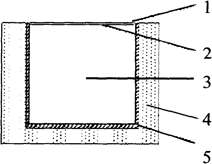
[0028] see figure 1 . Sample preparation for the emissivity and absorptivity determination of the filler: Grind the filler to be tested, then use acrylic, silicone and other adhesives to make a coating, and coat it on a 40mm×40mm×1mm aluminum substrate test piece. Dry it in the dusty place, and use FXL-1 Absorption / Emission Ratio Meter to measure its hair-to-emission rate and absorption rate.
[0029] The above-mentioned paint exposure experiment and the measurement of radiation cooling effect: adopt such as figure 1 The device shown was performed. When conducting the exposure experiment, the device was placed indoors for a day and night to achieve thermal equilibrium with the environment. During the experiment, the device coated with the paint was placed in the outdoor sunlight in a sunny or breezy weather, and the temperature inside each device and the ambient temperature were measured every half hour. Place the device under a clear night sky to test the temperature of t...
Embodiment 2
[0038] Adopt following proportioning ratio (mass ratio) mixture:
[0039] Alkaline earth metal carbonates 85%
[0040] Alkaline earth metal sulphates 5%
[0041] Alkaline earth metal silicate 5%
[0042] Alkaline earth metal aluminates 3%
[0043] Alkaline earth metal fluoroaluminate 2%
[0044] After it is ground into powder, the filler of the present invention is prepared, and then mixed and mixed according to filler: acrylic binder=1: 0.05 (mass ratio) to form a coating, which is coated on the aluminum plate substrate test piece of 40mm * 40mm * 1mm, and placed Dry it in an indoor environment, and use the FXL-1 absorption / emission ratio tester to measure the emission rate to 0.90 and the absorption rate to 0.45. use figure 1 The experimental device shown has a cooling effect of 7°C.
Embodiment 3
[0046] Adopt following proportioning ratio (mass ratio) mixture:
[0047] Alkaline earth metal carbonates 90%
[0048] Alkaline Earth Sulfates 3%
[0049] Alkaline earth metal silicate 2%
[0050] Alkaline earth metal aluminates 2%
[0051] Alkaline earth metal fluoroaluminate 3%
[0052]After it is ground into powder, the filler of the present invention is prepared, and then mixed and mixed according to filler: acrylic binder=1: 0.05 (mass ratio) to form a coating, which is coated on the aluminum plate substrate test piece of 40mm * 40mm * 1mm, and placed Dry it in the indoor environment, and use the FXL-1 absorption / emission ratio measuring instrument to measure the emission rate to 0.92 and the absorption rate to 0.42. use figure 1 The experimental device shown has a cooling effect of 9°C.
PUM
 Abstract
Description
Claims
Application Information
 - R&D Engineer
- R&D Manager
- IP Professional
- Industry Leading Data Capabilities
- Powerful AI technology
- Patent DNA Extraction
Browse by: Latest US Patents, China's latest patents, Technical Efficacy Thesaurus, Application Domain, Technology Topic, Popular Technical Reports.
© 2024 PatSnap. All rights reserved.Legal|Privacy policy|Modern Slavery Act Transparency Statement|Sitemap|About US| Contact US: help@patsnap.com