Time-domain parallel digital demodulation system

A digital demodulation and time-domain technology, applied in the field of digital information transmission, can solve problems such as high technological conditions, inability to meet general demodulation requirements, and huge investment

Inactive Publication Date: 2010-03-17
TSINGHUA UNIV
View PDF0 Cites 13 Cited by
  • Summary
  • Abstract
  • Description
  • Claims
  • Application Information

AI Technical Summary

Problems solved by technology

However, the premise that the above structure can work normally is that the local sampling clock and the symbol clock of the data must be 2N, N is a positive integer greater than 2, and general digital demodulation requires that the local sampling clock is fixed, so the APRX structure proposed by Andrew It can only handle a fixed data rate and cannot meet the general demodulation requirements; the third is based on the conve

Method used


Image

  • Time-domain parallel digital demodulation system
  • Time-domain parallel digital demodulation system
  • Time-domain parallel digital demodulation system

Examples


Embodiment 1

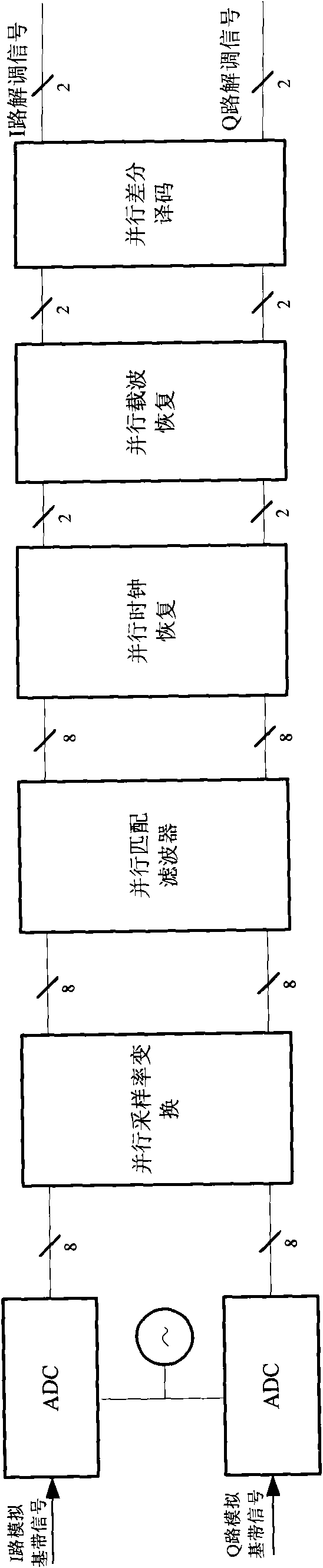
[0080] In this implementation case, the implementation of the demodulation method of the system of the present invention will be described by taking 8-channel parallel QPSK 4 times symbol rate digital demodulation as an example. figure 1 Shown is the system structure diagram of 8-way parallel demodulation, including: parallel sampling rate conversion module, parallel matched filter, parallel clock recovery loop, parallel carrier recovery loop, parallel differential decoder; the above modules are in accordance with figure 1 Connect in sequence as shown.

[0081] Module 1: The sampling signal obtained from the high-speed ADC is converted into 8 channels of parallel signals after serial-to-parallel conversion, which are represented by phase 0, phase 1, ..., phase 7 in chronological order. The ADC in this embodiment adopts a sampling rate of 2000MHz. The corresponding parallel signal is 250MHz for each channel. The signal first passes through the time-domain parallel sampling rat...

Embodiment 2

[0128] In this embodiment, the implementation of the demodulation method of the system of the present invention will be described by taking 4-channel parallel digital demodulation as an example.

[0129]Module 1: The sampling signal signal obtained from the high-speed ADC is converted into 4 channels of parallel signals through serial-to-parallel conversion. Through 4 parallel sampling rate conversion modules, the signal sampling rate is slightly higher than 4 times the symbol rate, and this embodiment takes 4.02 times the symbol rate.

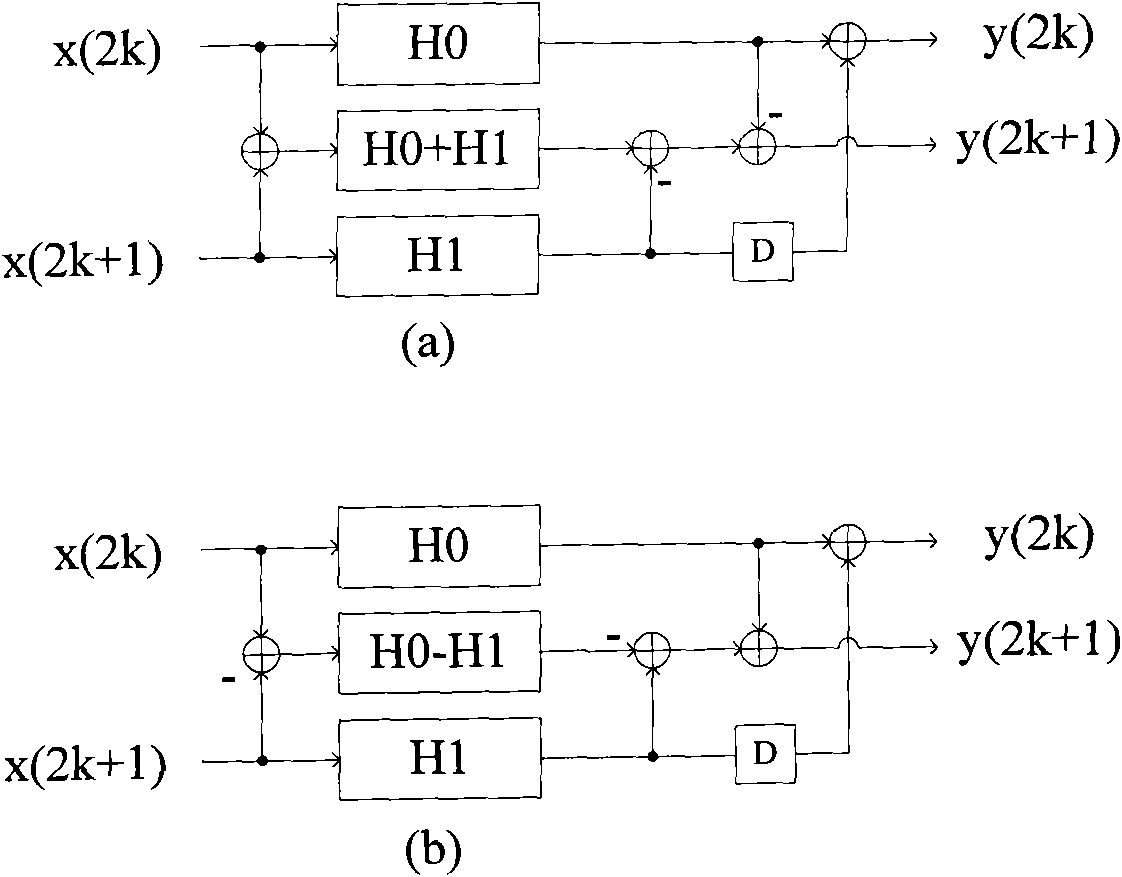
[0130] Module 2: Perform matched filtering on the signal that has undergone sampling rate conversion. The coefficients of the matched filter are the same as those in Example 1, using Figure 4 In the structure shown, this block precedes the parallel clock recovery loop.

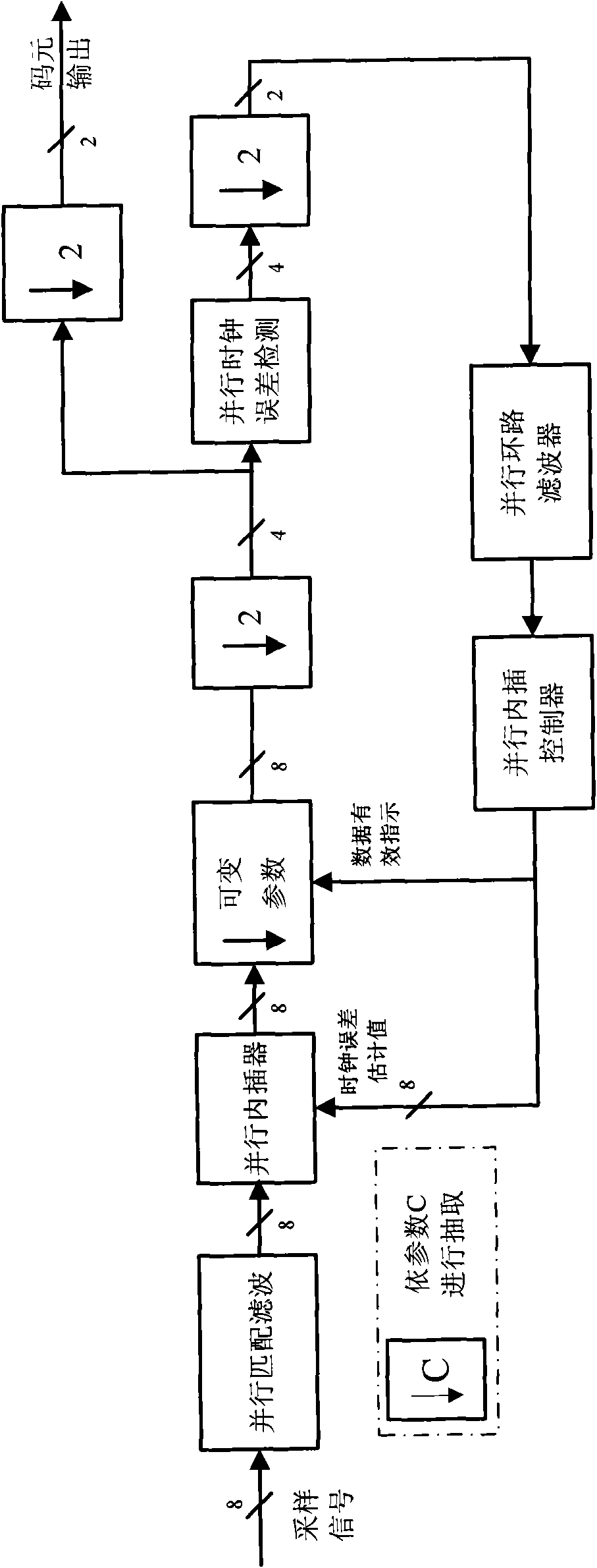
[0131] Module 3: Send the matched filtered signal into the parallel clock recovery loop. In this embodiment, the input signal of the clock recovery loop is 4 parallel signa...


PUM


Abstract

The invention discloses a time-domain parallel digital demodulation system, comprising a time-domain parallel sampling rate conversion module, a parallel matched filter module, a parallel clock recovery module, a time-domain parallel carrier recovery module and a differential decoding module, wherein the time-domain parallel sampling rate conversion module is used for converting the sampling rateof a sampling digital signal obtained by a high speed A/D converter, the parallel matched filter module is used for matched filtering the signal after sampling rate conversion, the parallel clock recovery module is used for carrying out timing recovery and re-sampling on the modulating signal after matched filtering, the time-domain parallel carrier recovery module is used for recovering the phasedifference and the frequency difference of the signal output by the parallel clock recovery module, and the differential decoding module is used for differential decoding the signal which is output by the time-domain parallel carrier recovery module and has phase ambiguity. The technical scheme of the invention can realize universal receiving demodulation with variable data rate and low cost, thus completing digital demodulation reaching up to 1200Mbps.

Description

technical field [0001] The invention relates to the technical field of digital information transmission, in particular to a digital demodulation system using a time-domain parallel demodulation algorithm, which is applied in the field of high-speed data transmission, such as high-speed remote sensing satellite signal transmission and reception. Background technique [0002] After entering the 21st century, the rise of aerospace technology and its application in the military has rapidly expanded the battlefield airspace from the atmosphere to outer space, expanded the fields of military activities and national defense security, and changed the form of modern warfare. Remote sensing satellite technology is an important part of it. It refers to the use of various sensors (such as visible light, infrared detection, radar, etc.) to obtain ground information on a space-based satellite platform. An applied science and technology of shape, size, location, properties and their relati...

Claims


Application Information

Patent Timeline
IPC IPC(8): H03D9/00H04B1/16
Inventor 张彧张维良杨再初杨知行潘长勇
Owner TSINGHUA UNIV
Why Eureka
Try Eureka