Auricular point detection system

A detection system and auricular point technology, applied in the directions of diagnostic recording/measurement, medical science, sensors, etc., can solve the problems of lack of information management, poor instrument accuracy, inability to count and analyze the resistance of acupuncture points, and reduce the volume of hardware circuits and hardware. The effect of small circuit size and simplified hardware circuit

Inactive Publication Date: 2010-04-07
TSINGHUA UNIV
View PDF2 Cites 3 Cited by
  • Summary
  • Abstract
  • Description
  • Claims
  • Application Information

AI Technical Summary

Problems solved by technology

However, similar to the previous invention, the hardware detection function of this invention is single, and it is difficult to meet the needs of accurate and quantitative diagnosis of acupoint function.
In addition, the hardware circuit design of this invention mainly uses discrete components, which is poor in maintenance and interchangeability, and uses early computers such as the Chinese Learning Machine. These computers have long since been eliminated, and there is no perfect system software, so it is inconvenient to use
In addition, there are some similar inventions, which have some obvious deficiencies in function and use, such as the lack of unified standards for the positioning of auricular points, the lack of standardization in the definition of auricular points; Poor, only the resistance of one acupoint is given, and the resistance information of adjacent acupoints is ignored; the statistics, analysis, and processing functions of the data are poor, and only the resistance of a single acupoint can be processed, and the anatomical The resistance of all acupoints in the subregions and nerve subregions is statistically and analyzed; it is difficult to save and compare the data after measurement, and there is no information management function; the system function is relatively simple, and most auricular point electrometers are only used for qualitative and real-time detection, and cannot be used conduct scientific research

Method used


Image

  • Auricular point detection system
  • Auricular point detection system
  • Auricular point detection system

Examples


Embodiment Construction

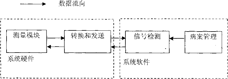
[0033] The present invention proposes an embodiment of a system for detecting auricular points, which consists of two parts: hardware circuit and software. In conjunction with each accompanying drawing, describe in detail as follows:

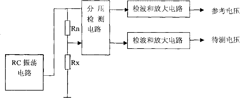
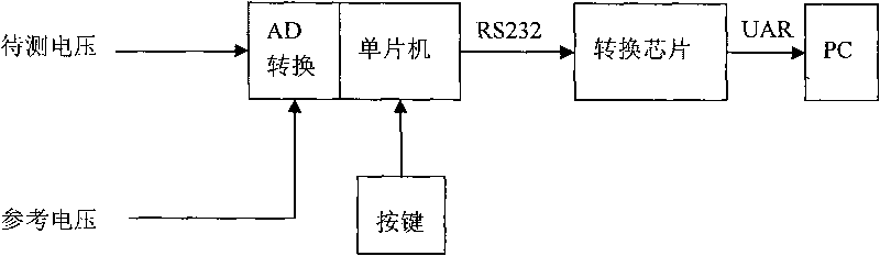
[0034] The overall structure of the hardware circuit of this embodiment is as follows: figure 1As shown, it consists of measurement module, conversion and transmission module. That is to say, it includes a measurement module composed of a measurement probe and its peripheral circuits, and a conversion and transmission module composed of a single-chip microcomputer and a UART level conversion chip. Wherein, the peripheral circuit of the measurement module includes an RC oscillator circuit, a voltage division measurement circuit and a detection amplifier circuit.

[0035] The measurement module is composed of a measurement probe and its peripheral circuit, and the measurement peripheral circuit is composed of an RC oscillator circuit, a voltage ...


PUM


Abstract

An auricular point detection system belongs to the technical field of auricular point impedance detection and is characterized by comprising a measurement part and a single chip part which are mutually connected in serial, wherein the measurement part comprises a measurement probe pen, an RC oscillating circuit, a partial pressure measuring circuit and a demodulation amplifying circuit which are orderly connected in serial; and the single chip part comprises an MCU single chip, a UART level conversion chip and a signal detecting module arranged in the MCU single chip, which are orderly connected in serial. The auricular point detection system uses the auricular point resistance distribution graph to display the measurement result and uses red to represent the low resistance area of the auricular point resistance so as to position a focus area; and meanwhile, the hardware circuit of the system is greatly simplified so as to increase the quantitative accuracy and precision.

Description

technical field [0001] The invention belongs to the technical fields of electronics, computer and signal processing, in particular to an auricular point detector which uses a pseudo-color topographic distribution map of auricular point impedance to evaluate whether the auricular point is normal. Background technique [0002] Auricular points are the parts where the surface of the skin of the auricle communicates with the viscera, meridians, tissues, organs, and limbs of the human body. The parts on the auricle that reflect the physiological functions and pathological changes of the human body are collectively called auricular points. The distribution of auricular points is regular. The arrangement on the front and outer sides of the auricle is like an inverted fetus in the womb, with the head facing down, the buttocks and limbs facing up, and the chest and torso in the middle. The shape of the internal organs in the representative area of ​​the auricle is similar to the sha...

Claims


Application Information

Patent Timeline
Patent Type & Authority Applications(China)
IPC IPC(8): A61B5/053
Inventor 宫琴陈曦刘京雷叶大田孙文生
Owner TSINGHUA UNIV
Why Eureka
Try Eureka