
Thin-type soft packaging super capacitor

A supercapacitor and flexible packaging technology, applied in the direction of capacitors, electrolytic capacitors, capacitor parts, etc., can solve the problems of capacitor mass specific energy decline, achieve the effect of improving the safety of use, reducing current density, and improving mass specific energy

Active Publication Date: 2012-05-30
中国船舶重工集团公司第七一二研究所
View PDF3 Cites 0 Cited by
  • Summary
  • Abstract
  • Description
  • Claims
  • Application Information

AI Technical Summary

Problems solved by technology

However, supercapacitors with this structure must reserve a blank current collector of sufficient width on both sides of the stack as the connection area between the positive and negative terminals, and this part of the space cannot be used to store energy.
Therefore, the mass-to-energy ratio of this capacitor is greatly reduced while the mass-to-power ratio is increased.

Method used


Image

  • Thin-type soft packaging super capacitor
  • Thin-type soft packaging super capacitor
  • Thin-type soft packaging super capacitor

Examples


Embodiment 1

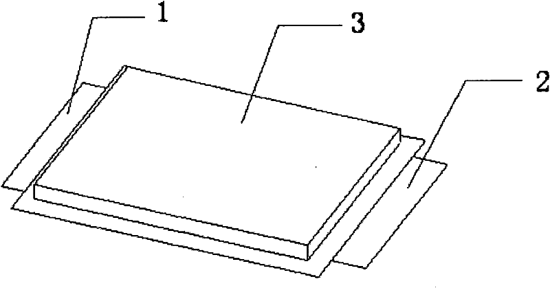
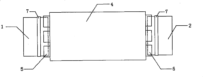
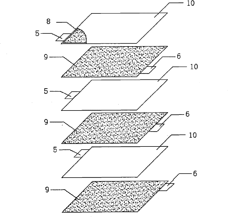
[0027] Embodiment 1: as figure 1 , 2 As shown in , 3, a thin flexible package supercapacitor is composed of flexible package film 3, electrolyte, capacitor core 4, positive pole tab 1 and negative pole tab 2; Sheets 9 are stacked one after the other to form, the present embodiment is for example figure 2 , 3 As shown, the capacitor core 4 is formed by stacking the positive electrode sheet 8 and the negative electrode sheet 9 wrapped in the porous separator 10 in the order: positive / negative / positive / negative...; there is a blank space at one end of each positive electrode sheet 8 Positive current collector 5 , a blank negative current collector 6 at one end of each negative plate 9 ; positive tab 1 and negative tab 2 are located at both ends of capacitor core 4 . The positive electrode sheet 8 and the negative electrode sheet 9 are 2 to 10 groups, and the present embodiment is 3 groups respectively; the positions of the blank positive electrode current collectors 5 of the ...

Embodiment 2

[0028] Embodiment 2: Different from the above embodiment, the positive electrode sheet 8 and the negative electrode sheet 9 are in two groups; the thickness of the positive electrode tab 1 is 5 times the thickness of the blank positive electrode current collector 5; the capacitor core 4 is two The number of positive pole tab 1 and negative pole tab 2 at the end is three respectively.

Embodiment 3

[0029] Embodiment 3: Different from the above embodiment, the positive electrode sheet 8 and the negative electrode sheet 9 are 10 groups; the thickness of the positive electrode tab 1 is 30 times the thickness of the blank positive electrode current collector 5; the capacitor core 4 is two The number of positive pole tab 1 and negative pole tab 2 at the end is 5 respectively.

[0030] More specific instructions are as follows:

[0031] Refer to attached image 3 , select aluminum foil with a thickness of 15-30 μm as the blank positive electrode current collector 5 and the blank negative electrode current collector 6, and coat the electrodes based on activated carbon and conductive carbon black on both sides of the blank positive electrode current collector 5 and the blank negative electrode current collector 6 respectively. Material. According to the size requirements, the positive electrode sheet 8 and the negative electrode sheet 9 are cut and rolled into shape, and a par...


PUM


Abstract

The invention relates to a thin-type soft packaging super capacitor, which comprises a soft packaging thin film, electrolytic solution, a capacitor chip, an anode ear and a cathode ear, wherein the capacitor chip comprises an anode piece, a porous isolation film and a cathode piece which are mutually overlapped together in turn, the end potion of one end of each anode piece is provided with a blank anode current collector, the blank cathode current collector is arranged on the end portion of one end of each cathode piece, and the anode ear and the cathode ear are arranged on two ends of the capacitor chip. The thin-type soft packaging super capacitor effectively increases the thickness and the overall area of the pole ear, reduces heating capacity, avoids short circuit between the anode ear and the cathode ear, and lowers welding thickness. And the super capacitor has the characteristics of high energy density, safe use and convenient welding and processing, and is suitable for big current to charge and discharge.

Description

technical field [0001] The invention relates to a thin soft-packaged supercapacitor, which belongs to the technical field of supercapacitors. Background technique [0002] A supercapacitor is a new type of energy storage device between a physical capacitor and a battery. It has a much higher energy density than a traditional capacitor and a much higher power density than a battery. It has a combination of long life, high power density, and wide operating temperature. Range, fast charging and other features in one. These excellent properties of supercapacitors make them widely used in transportation, radio communication, military, clean energy systems and other fields. [0003] With the continuous expansion of the application field of supercapacitors, it is increasingly required that supercapacitors can be placed in a limited space, which puts forward higher requirements for the volume and shape of supercapacitors. When the traditional metal casing is used as the external p...

Claims


Application Information

Patent Timeline
Patent Type & Authority Patents(China)
IPC IPC(8): H01G9/155H01G9/08H01G9/058H01G9/016H01G11/70H01G11/74
CPCY02E60/13
Inventor 范晶郭丽宋朝文管道安姚国富
Owner 中国船舶重工集团公司第七一二研究所
Learn More