Smoke waste heat recovery system of power station boiler and method thereof

A technology of waste heat recovery system and power plant boiler, which is applied in the direction of preheating, feed water heater, lighting and heating equipment, etc. It can solve the problems of not considering the concentration of flue gas ash, easy ash accumulation in heat exchanger, and waste of fuel, etc., to avoid Effects of low-temperature corrosion and condensation, improvement of equipment safety, and reduction of coal consumption for power supply

Inactive Publication Date: 2011-01-19
SHANGHAI JIAO TONG UNIV
View PDF0 Cites 1 Cited by
  • Summary
  • Abstract
  • Description
  • Claims
  • Application Information

AI Technical Summary

Problems solved by technology

[0003] After searching the existing literature, it was found that "Journal of Changchun University of Technology" published in July 2007 "Power Plant Boiler Exhaust Heat Recovery Energy Saving Technology" provided a power plant boiler exhaust heat recovery energy saving device, but the control of the device The single-way baffle plate controlled by a relatively cumbersome electric actuator has the disadvantage that the flue gas cannot completely enter the bypass flue in actual operation, and the consequences of easy ash accumulation in the heat exchanger caused by the relatively large ash concentration of the flue gas are not considered.
[0004] After searching, it was found that "Northeast Electric Power Technology" published in April 2006 "Analysis of Economic Benefits of Installing Low-voltage Economizers in Thermal Power Plants" provided a method for installing economizers in thermal power plants, but in this method It does not take into account that the acid dew point temperature of boiler exhaust flue gas varies with factors such as the environment and coal type, and at the same time the temperature of the heated return water cannot be controlled, which is likely to cause waste of fuel

Method used


Image

  • Smoke waste heat recovery system of power station boiler and method thereof
  • Smoke waste heat recovery system of power station boiler and method thereof
  • Smoke waste heat recovery system of power station boiler and method thereof

Examples


Embodiment Construction

[0019] The system of the present invention is further described below in conjunction with the accompanying drawings. This embodiment is implemented on the premise of the technical solution of the present invention, and detailed implementation methods and specific operating procedures are provided, but the protection scope of the present invention is not limited to the following Example.

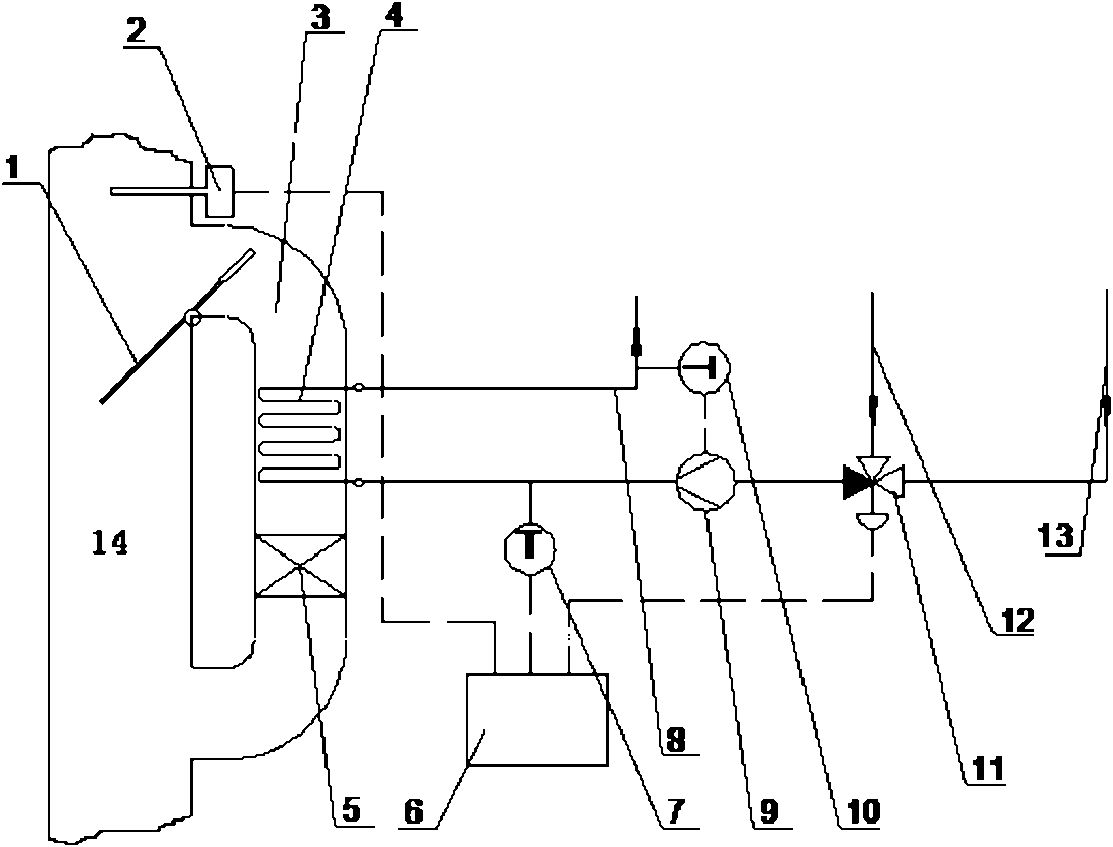
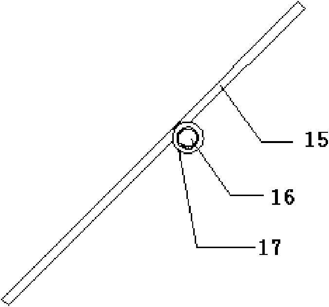
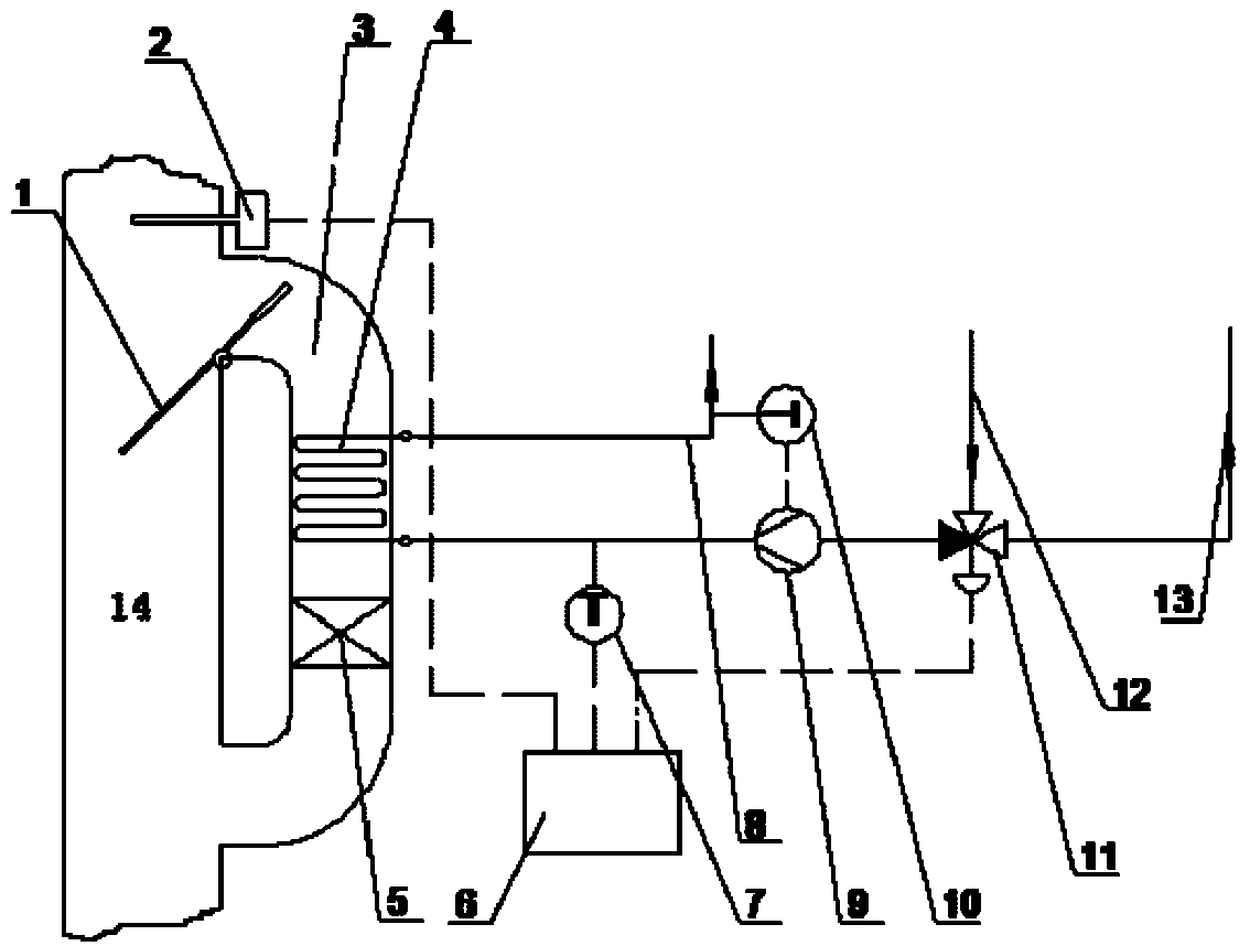
[0020] Such as figure 1 As shown, the waste heat recovery system for power station boilers involved in this embodiment includes: baffle plate 1, acid dew point meter 2, bypass flue 3, return water heater 4, bypass flue fan 5, controller 6, return Water inlet temperature sensor 7, return water introduction pipeline 8, return water frequency conversion water pump 9, return water outlet temperature sensor 10, electric three-way regulating valve 11, medium temperature return water outlet pipeline 12 and low temperature return water outlet pipeline 13, among which : The bypass flue 3 is closely c...


PUM


Abstract

The invention discloses a smoke waste heat recovery system of a power station boiler and a method thereof, belonging to the technical field of energy saving. The system comprises a bypass flue, a baffle plate, an acid dew point instrument, a backwater heater, a bypass flue fan, a controller, a backwater inlet temperature sensor, a backwater leading-in pipeline, a backwater frequency conversion water pump, a backwater outlet temperature sensor, an electric three-way adjusting valve, a mediate-temperature leading-out pipeline and a low-temperature backwater leading-out pipeline. The recovery method is characterized in that the controller adjusts the electric three-way adjusting valve to enable the acid dew point temperature to be less than the temperature of backwater entering the backwaterheater all the time; and the temperature of backwater flowing out of the backwater heater is ensured to be equal to the temperature threshold value of a backwater outlet of the system through a temperature control transducer. The invention avoids dust accumulating on a backwater heat exchanger, ensures that smoke completely enters the bypass flue, and avoids the low-temperature corrosion and dew formation of a heat exchanging system. The requirement of the system on the backwater temperature is satisfied through changing the rotate speed of the backwater frequency conversion water pump so that the steam extraction capacity is reduced, and the coal consumption for power supply is also reduced.

Description

technical field [0001] The present invention relates to a system and a method in the field of energy-saving technology, in particular to a power plant boiler exhaust heat recovery system and a method thereof. Background technique [0002] For power plant boilers, exhaust gas loss is the biggest loss of boiler thermal efficiency, of which high flue gas temperature is the main reason. Since the acid dew point of the flue gas in the boiler is related to many factors such as coal type and water content, air temperature and humidity, excess air coefficient, sulfur content in coal type and ash content, fly ash ratio, etc., in the boiler design, take into account Affected by the acid dew point, in order to avoid low-temperature corrosion of the tail heating surface, the value of the flue gas temperature is generally higher, so that there is inevitably a waste of flue gas temperature margin. Secondly, the last heating surface of the boiler is an air preheater, and the wall temperat...

Claims


Application Information

Patent Timeline
Patent Type & Authority Patents(China)
IPC IPC(8): F22D1/00F22D1/02F22D1/12
Inventor 陆方
Owner SHANGHAI JIAO TONG UNIV
Why Eureka
Try Eureka