Dual stator and rotor permanent magnet synchronous motor and assembling method thereof

A technology for permanent magnet synchronous motors and assembly methods, which is applied in the direction of electromechanical devices, manufacturing motor generators, electrical components, etc., can solve the problems of increased difficulty in the stator winding process, reduced work reliability, and increased rotor strength, and achieves Overcome the effects of small power capacity, error reduction, and torque disturbance reduction

Inactive Publication Date: 2010-05-05
FOSPOVA +1
View PDF0 Cites 8 Cited by
  • Summary
  • Abstract
  • Description
  • Claims
  • Application Information

AI Technical Summary

Problems solved by technology

However, it is necessary to increase the number of pole pairs in the circumferential direction while increasing the diameter of the stator to increase the power of the motor. If the number of pole pairs is large, the magnetic density can be increased, but the mechanical speed of the motor at the same power supply frequency will decrease. For high-speed synchronous For motors, this increases the difficulty of high-speed motors; if the number of pole pairs is small, the magnetic density will decrease, which will restrict the increase in motor power; if the diameter of the rotor is increased, the linear speed of the rotor surface will increase, because the centrifugal force is proportional to the square of the radius Proportional, resulting in increased rotor strength requirements and reduced operational reliability
Therefore, it can only be considered to increase the motor power by increasing the length of the motor stator and rotor. However, as the length of the motor stator and rotor increases, the difficulty of the stator winding process increases. According to the current design and manufacturing technology level of the permanent magnet synchronous high-speed motor The power of the motor can be increased to a certain extent, but the amount of increase is very limited. It is usually only suitable for motors less than 200kw. It is very difficult to increase the motor power to 315kw and the speed to 18000rpm by increasing the length and diameter of the stator and rotor of a single motor.

Method used


Image

  • Dual stator and rotor permanent magnet synchronous motor and assembling method thereof
  • Dual stator and rotor permanent magnet synchronous motor and assembling method thereof
  • Dual stator and rotor permanent magnet synchronous motor and assembling method thereof

Examples


Embodiment Construction

[0037] The dual-stator-rotor permanent magnet synchronous motor of the present invention will be further described in detail below in conjunction with the accompanying drawings.

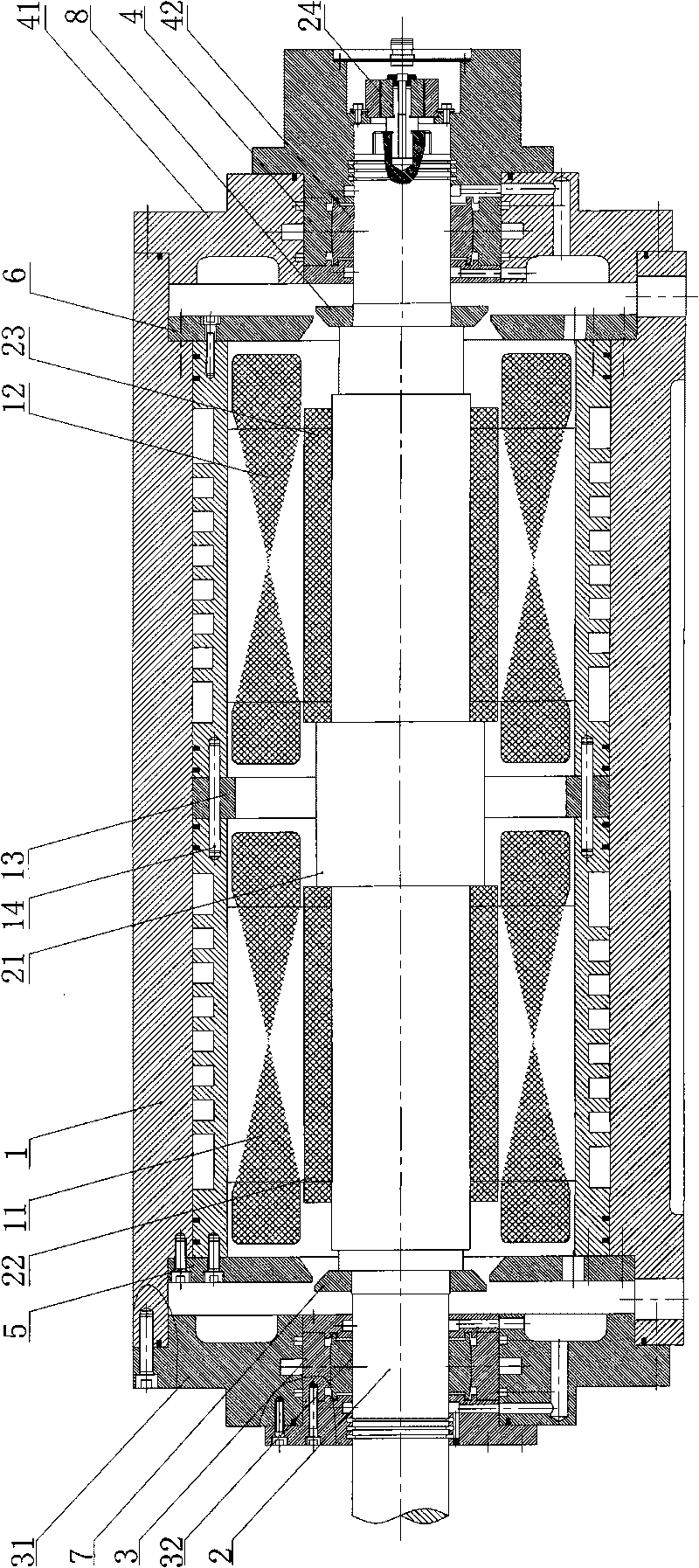
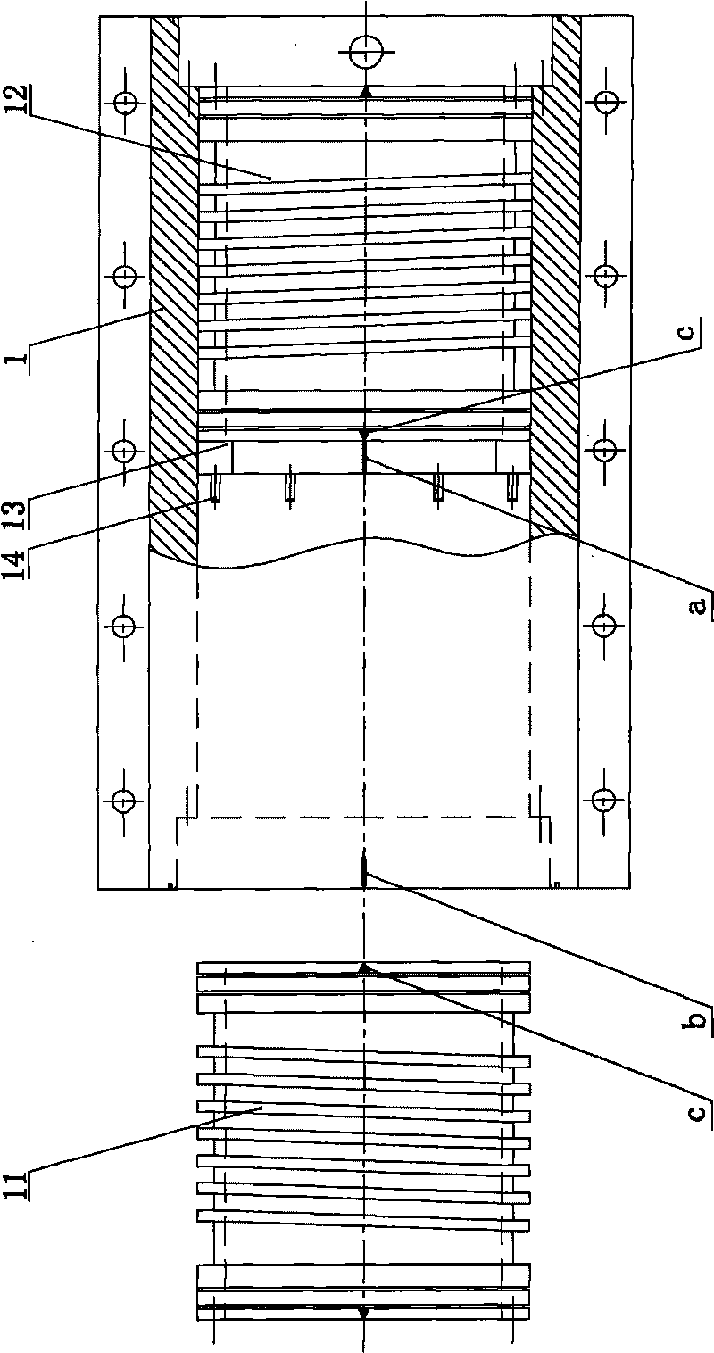
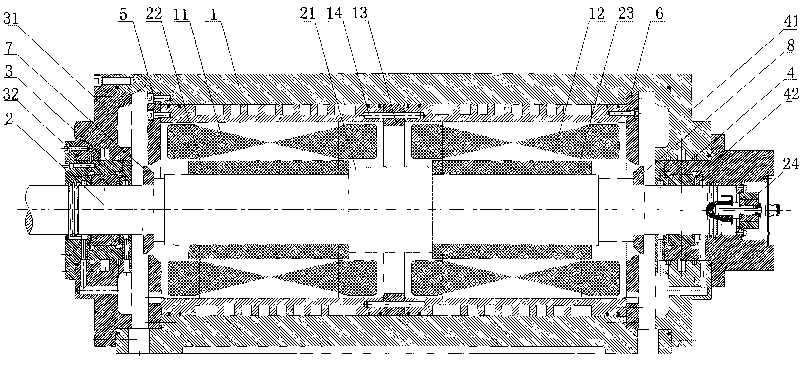
[0038] Such as figure 1 and figure 2 As shown, the dual-stator-rotor permanent magnet synchronous motor of the present invention includes a motor casing 1, a motor main shaft 2, a front end cover assembly 3 and a rear end cover assembly 4, the middle part of the motor main shaft 2 is provided with a shaft shoulder 21, and the motor main shaft 2 The upper sleeve is equipped with a motor front rotor 22 and a motor rear rotor 23. The motor front rotor 22 and the motor rear rotor 23 are respectively close to the two sides of the shaft shoulder 21. The motor box 1 is equipped with a motor front stator 11, a motor rear stator 12 and a guide ring. 13. The guide ring 13 is set between the front stator 11 of the motor and the rear stator 12 of the motor. The front stator 11 of the motor and the rear stator ...


PUM


Abstract

The invention discloses a dual stator and rotor permanent magnet synchronous motor. The middle part of the motor main shaft is provided with a shaft shoulder, the main shaft is sheathed with a front rotor and a back rotor adjacent to two sides of the shaft shoulder, a case body is internally provided with a front stator, a back stator and a guide ring, the front stator and the back stator are located by the guide ring and a guide pin, the initial phase position of the front stator and the back stator are aligned, and the motor has large power and high rotation speed. The invention also discloses an assembling method of the dual stator and rotor permanent magnet synchronous motor, in which the main shaft is mounted with two rotors that are adjacent to the shaft shoulder at the middle part of the main shaft; the case body is internally provided with two stators and a guide ring, the guide ring and the stators cooperate to drill a guide hole, a mark aligned with the initial phase position on the stators is arranged on the guide ring, the guide ring is fixed with a stator while keeping the initial phase position, the stator is inserted into the case body, and a mark corresponding to the initial phase position on the stator is made on the case body, the other stator is inserted into the case body while keeping aligned with the mark on the case body; the main shaft is inserted into the stator while keeping that the rotors correspond to the stators; and a front cover assembly and a back cover assembly are mounted. The method can cause the initial phase position of the two stators to be aligned with each other.

Description

technical field [0001] The invention relates to the field of mechanical manufacturing, in particular to a permanent magnet synchronous high-speed high-power motor and an assembly method thereof. Background technique [0002] Large-scale high-speed rotating mechanical equipment is widely used in national defense, metallurgy, mining, chemical industry and other fields, such as various large fans, turbo compressors, ship power systems and centrifugal compressors. Large-scale high-speed rotating machinery and equipment occupy an extremely important position in my country's national economy. [0003] Traditional high-speed rotating mechanical equipment mostly uses a transmission system (belt drive, gearbox drive, etc.) to achieve speed increase, and the power source is mostly an ordinary motor. Rotating mechanical equipment using this type of transmission mode allows a lower maximum operating speed. Due to the complexity of the transmission system, the vibration and noise are la...

Claims


Application Information

Patent Timeline
Patent Type & Authority Applications(China)
IPC IPC(8): H02K16/00H02K5/04H02K11/00H02K5/16H02K15/00H02K11/21
Inventor 熊万里侯志泉罗春龙蒋旭光阳雪兵吕浪
Owner FOSPOVA
Why Eureka
Try Eureka